223
Simulation
Explanation
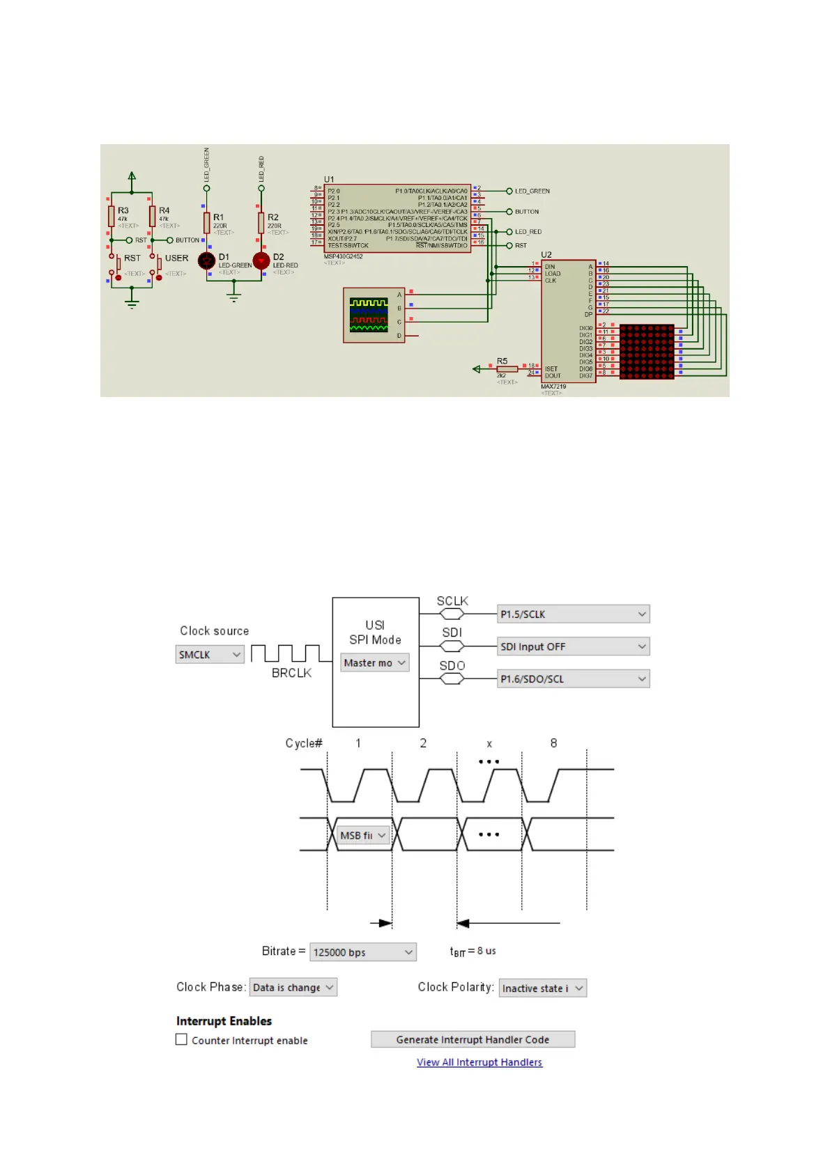
USI-based SPI is best realized with a MAX7219-based dot-matrix display and this demo is based on it.
USI is setup for SPI mode. Every time USI is initialized it is disabled first just like other hardware. We,
then, proceed to setup the SPI data transfer properties like SPI clock speed, device role, mode of
operation, etc. Finally, USI is enabled for data transfer over SPI bus.