105
Explanation
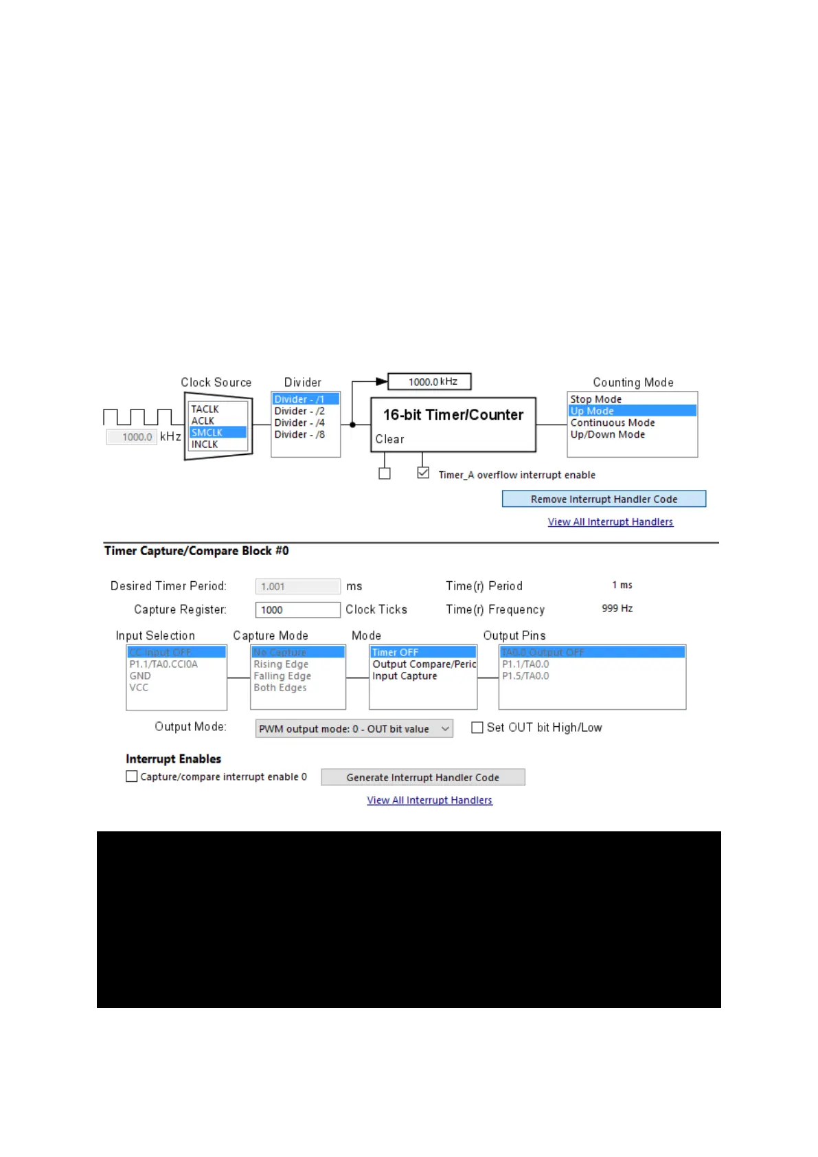
In this demo, Timer_A3 is configured as an up counting timer, i.e. it will count from 0 to a top value
determined by the contents of TA0CCR0 register. Again, SMCLK is used as the clock source for the
timer but this time it is not scaled down. SMCLK is set to 1 MHz and so does Timer_A3. This means
every one tick of Timer_A3 is one microsecond in duration. To make it appear that all four seven
segments are simultaneously on without any flickering, we need to scan them fast enough to fool our
eyes. We also have to ensure that each segment gets enough time to light up properly. In order to do
so we need to scan the segments at one millisecond rate. To get one millisecond from a timer with
one microsecond tick interval, we have to load it with 999, not 1000. This is so because from 0 to 999
the total number of ticks is 1000. In short, 1000 times 1 microsecond equals 1 millisecond. Thus,
TA0CCR0 is loaded with 999.
/* TA0CCR0, Timer_A Capture/Compare Register 0 */
TA0CCR0 = 999;
/*
* TA0CTL, Timer_A3 Control Register
*
* TASSEL_2 -- SMCLK
* ID_0 -- Divider - /1
* MC_1 -- Up Mode
*/
TA0CTL = TASSEL_2 | ID_0 | MC_1 | TAIE;