215
USI SPI – Interfacing MAX7219
SPI communication is an onboard synchronous communication method. It is used for communicating
with a number of devices including sensors, TFT displays, port expanders, PWM controller ICs, memory
chips, addon support devices and even other microcontrollers.
In a SPI communication bus, there is always one master device which generates clock and select
slave(s). Master sends commands to slave(s). Slave(s) responds to commands sent by the master. The
number of slaves in a SPI bus is virtually unlimited provided that there is no issue with slave selection
hardware and bus speed. Except the chip selection pin, all SPI devices in a bus can share the same
clock and data pins.
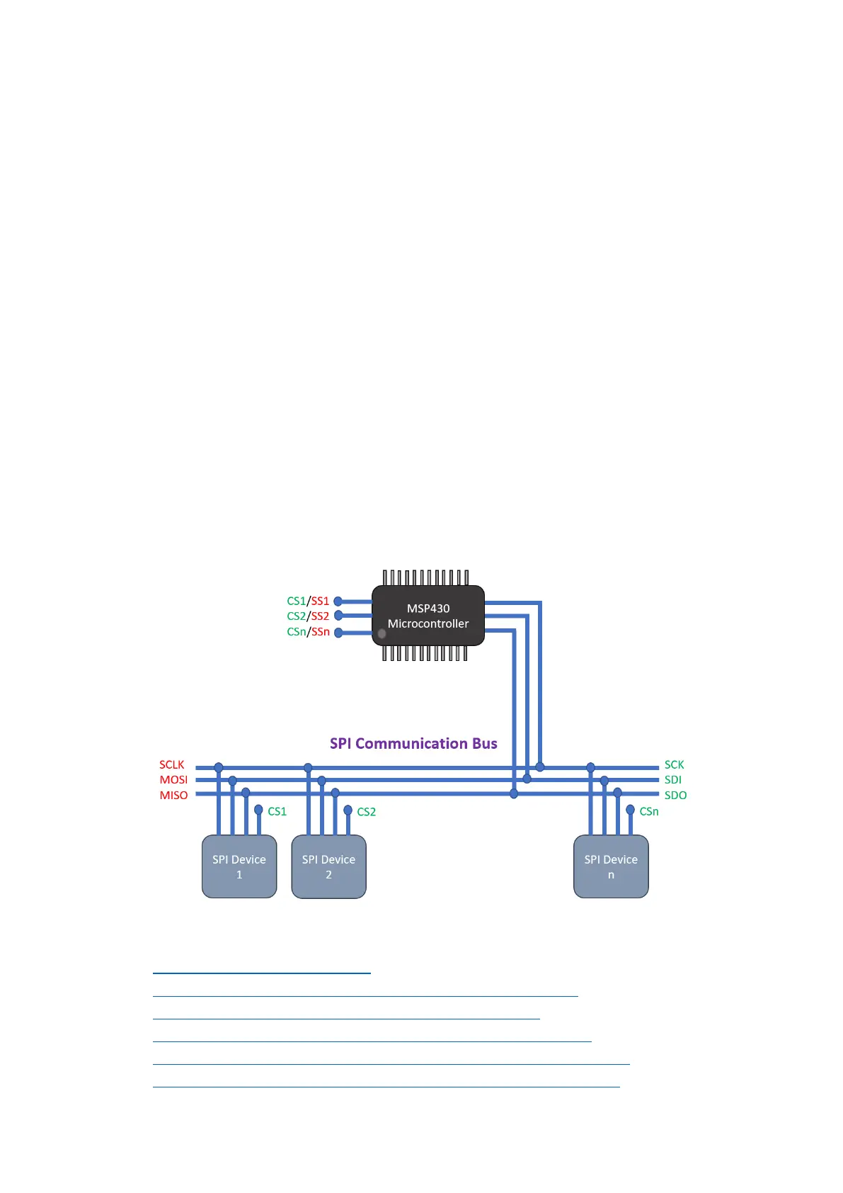
Typical full-duplex SPI bus requires four basic I/O pins:
• Master-Out-Slave-In (MOSI) connected to Slave-Data-In (SDI).
• Master-In-Slave-Out (MIS0) connected to Slave-Data-Out (SDO).
• Serial Clock (SCLK) connected to Slave Clock (SCK).
• Slave Select (SS) connected to Chip Select (CS).
The diagram below illustrates SPI communication with a MSP430 micro. The green labels are for slaves
while the red ones are for the master or host MSP430 micro.
In general, if you wish to know more about SPI bus here are some cool links:
• https://learn.mikroe.com/spi-bus/
• https://learn.sparkfun.com/tutorials/serial-peripheral-interface-spi
• http://ww1.microchip.com/downloads/en/devicedoc/spi.pdf
• http://tronixstuff.com/2011/05/13/tutorial-arduino-and-the-spi-bus/
• https://embeddedmicro.com/tutorials/mojo/serial-peripheral-interface-spi
• http://www.circuitbasics.com/basics-of-the-spi-communication-protocol/