303
Simulation
The model for BH1750FVI is not available in Proteus VSM and so it cannot be simulated. Only the
pinouts are shown in the schematic below.
Explanation
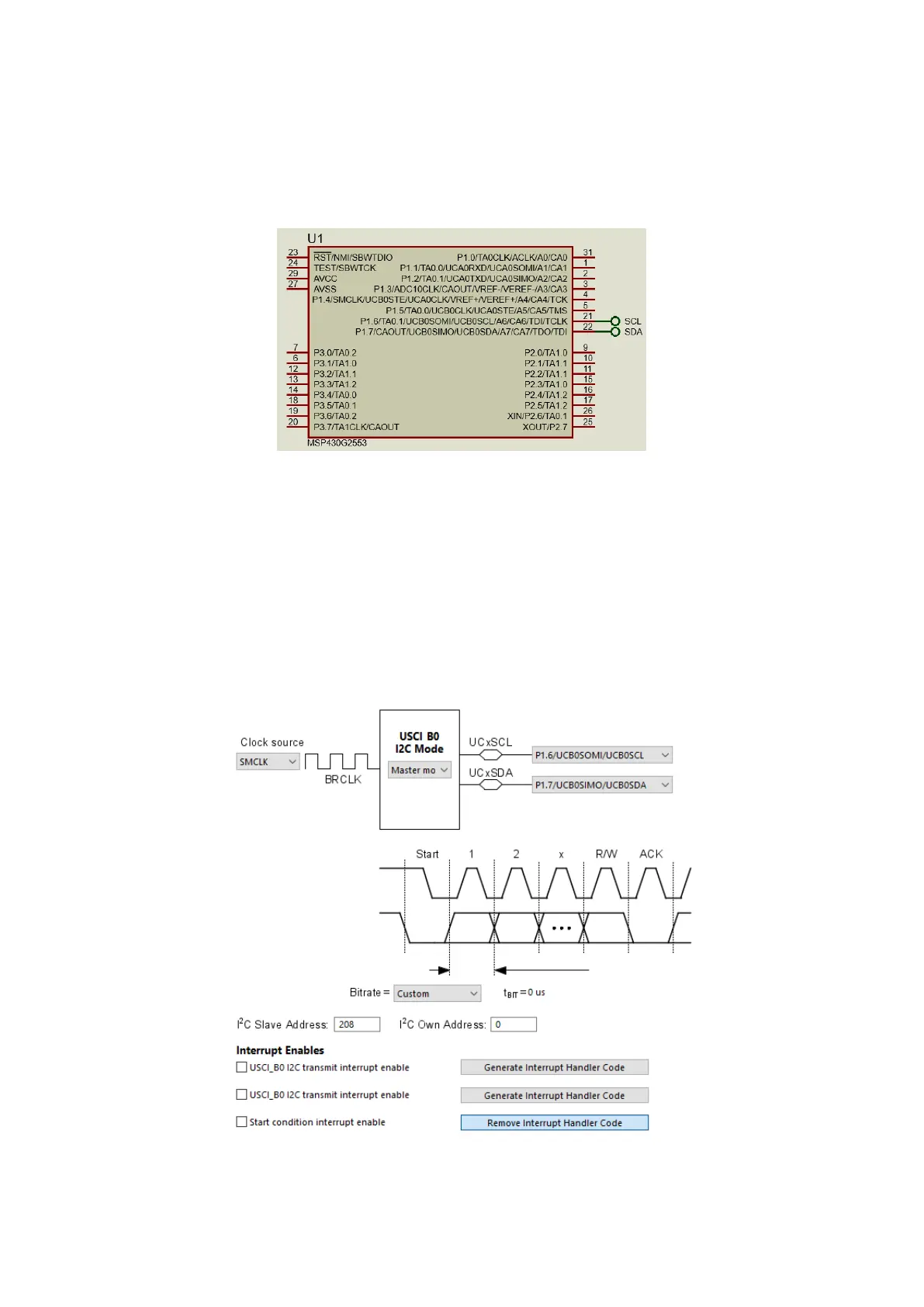
Just like USCI SPI setup, Grace is used for setting the basic parameters for USCI I2C communication.
Note only USCI_B0 supports I2C communication unlike USCI SPI communication. Since our MSP430
micro is the master device in the I2C bus, USCI module is configured as I2C master. One particular
thing to observe is the I2C Slave Address. Here as shown in the screenshot below, it is 208. This is not
an important figure. Same goes for the I2C Own Address part. No interrupts are to be used and so
none of them are enabled.
Out of the configuration set by Grace, I2C pins are set also in the I2C initialization function. This should
be done manually before initializing the USCI hardware.