146
Explanation
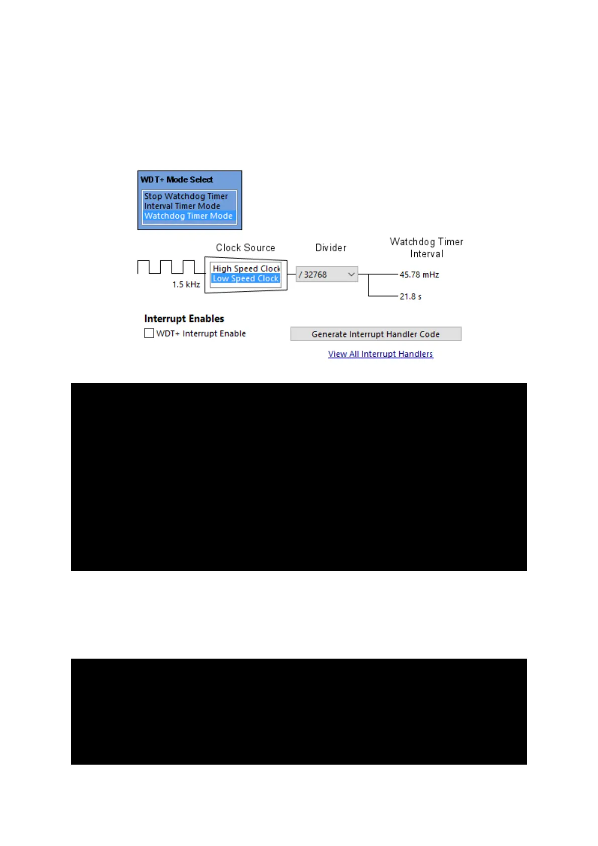
Unlike previous timer examples, 12 kHz ACLK is used. ACLK is divided by 8 to make it 1.5 kHz low speed
clock source for the WDT+ module. This clock is further prescaled by 32768 to get a WDT+ timeout of
about 22 seconds.
/*
* WDTCTL, Watchdog Timer+ Register
*
* WDTPW -- Watchdog password
* ~WDTHOLD -- Watchdog timer+ is not stopped
* ~WDTNMIES -- NMI on rising edge
* ~WDTNMI -- Reset function
* ~WDTTMSEL -- Watchdog mode
* ~WDTCNTCL -- No action
* WDTSSEL -- ACLK
* ~WDTIS0 -- Watchdog clock source bit0 disabled
* ~WDTIS1 -- Watchdog clock source bit1 disabled
*
* Note: ~<BIT> indicates that <BIT> has value zero
*/
WDTCTL = WDTPW | WDTSSEL;
In the main loop, P1.0 toggles without any issue. WDT+ is regularly refreshed. However, when the user
button is pressed, WDT+ is no longer refreshed and P1.6 LED is toggled inside a simulated undesired
loop. P1.0 LED appears to have gotten stuck. This causes the WDT+ to cross maximum timeout limit
and thereby trigger a reset.
P1OUT ^= BIT0;
_delay_cycles(60000);
WDTCTL = WDTPW | WDTCNTCL;
if((P1IN & BIT3) == !BIT3)
{
WDTCTL = WDTPW | WDTSSEL;