119
Timer Input Capture
In many cases, it is needed to measure the timing info like period, frequency, duty cycle, etc of an
incoming signal. Based on these data we can find out the RPM of a robot’s wheel, the pulse widths of
an IR remote stream carrying command information, the frequency of AC mains, the patterns of an
incoming waveform, etc. Hence comes the purpose of timer input captures.
We know that Timer A3 has three such CC channels and so there are three capture inputs per Timer
A module. We can use these channels to capture incoming waveforms of unknown frequencies/duty
cycles and have them measured with respect to a known clock like SMCLK.
Again a few things must be observed before using MSP430 input capture hardware:
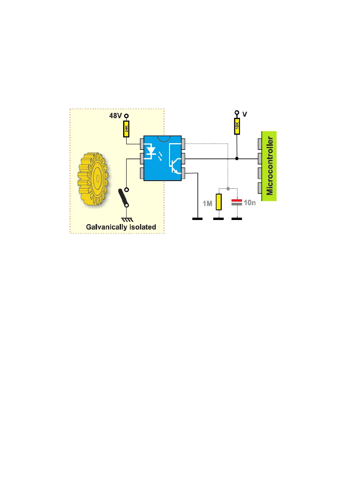
• Signals coming to input pins must never cross the max. VDD limit or fall below ground level
(i.e. sensing negative potentials).
• It is better to galvanically isolate input pins if they are to sense external high voltage signals.
• Input pins must not be left floating.
• Unless needed, it is wise not to use RC filters for inputs.
• Input capture pins are limited remappable just like PWM pins.
• Timer clock must be set as such that we get maximum measurement resolution without
compromising reliability.
• Timer overruns/overflows must be taken into account.
• Timer capture inputs can be tied to power pins internally and connecting so results in no
measurements. When not capturing anything, select stop mode and clear the timer.