164
Simulation
Explanation
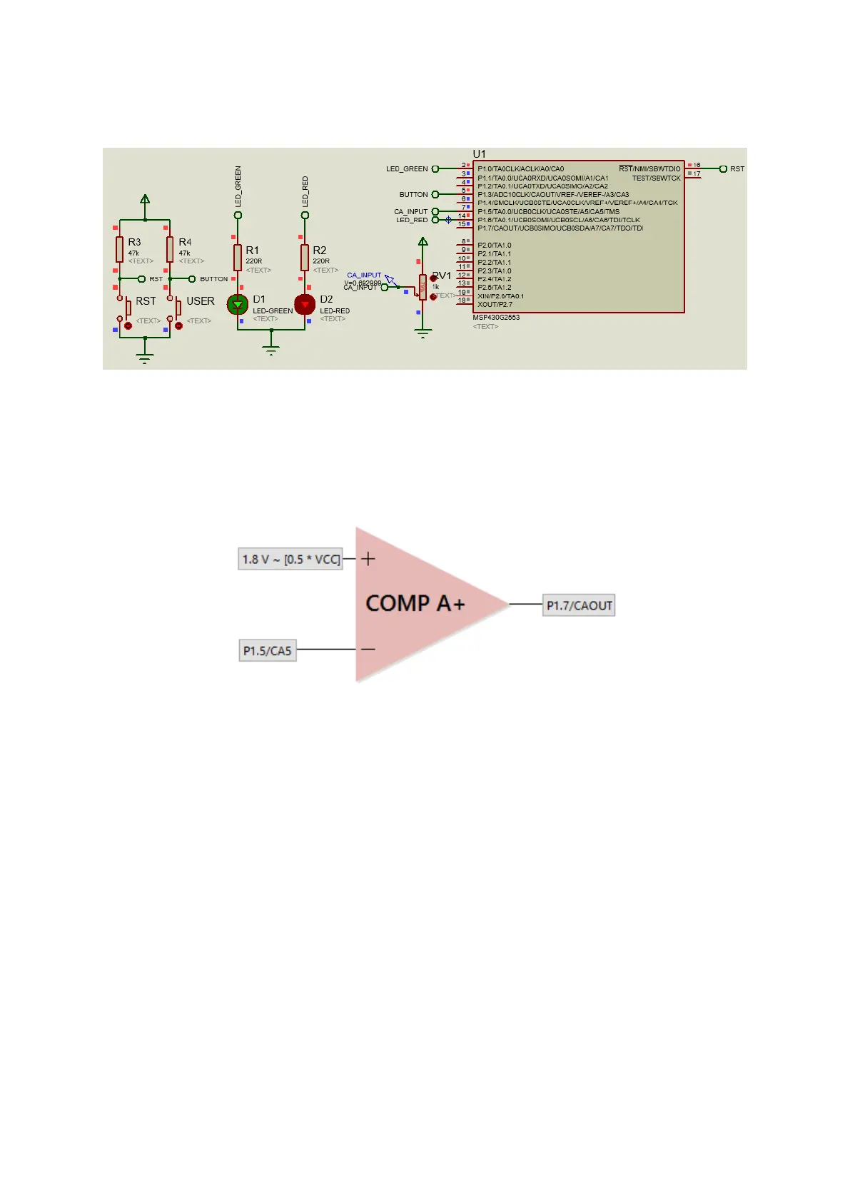
For this demo, a MSP430G2553 is used. Launchpad board’s LEDs are used and additionally a
potentiometer (pot) is tied to P1.5. The pot has its ends connected to VDD and GND. The internal
connection is as shown below:
The code dictates that Comp A+ interrupt will occur on falling edges only. Now the question is whose
falling edge? Certainly not the inputs. Interrupt will only occur when there is a logic high-low transition
on CAOUT pin – P1.7 here. According to the simplified comparator internal connection shown above,
this transition will occur only when P1.5’s voltage exceeds that of the 1.8V reference. When a
Comp_A+ interrupt occurs, P1.0’s logic state is toggled.
One thing to note here is the fact that though it is not mandatory to clear comparator interrupt flag,
it is wise to clear it after processing the interrupt request.