212
Note that all channels are enabled since the topmost channel we have measured here is the Measure
VCC channel but intentionally the memory block size is set 1 instead of 12 and only one external
channel is enabled. Well, there are some proof-of-concepts to show. The first proof-of-concept is the
fact that since we have to set memory block size and memory pointer on our own in the initialization
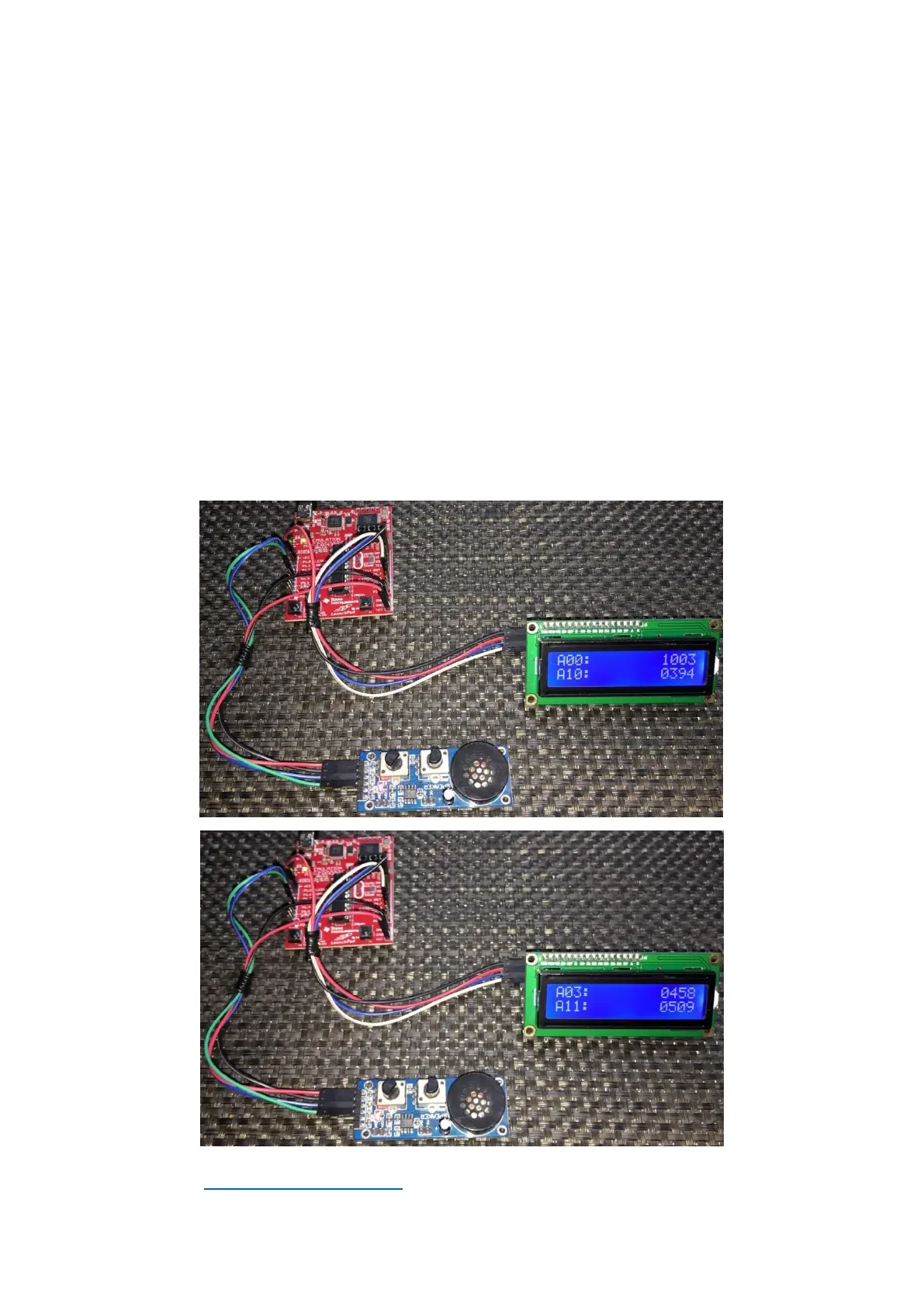
code, it doesn’t matter what these values are in Grace. Secondly, only external channel A3 is sensed
since its external I/O is enabled. The rest of the external channels are ignored. This is why A0 reads
floating values when the code runs because its external I/O to ADC is disconnected and further more
it is used to blink the onboard Launchpad LED connected with it. Channel A10 (internal temperature
sensor) and A11 (internal VCC sensor) are internal channels and so are not dependent on external
I/Os. These channels read as they should. Despite scanning all channels, we can decide which ones we
need. Here I demoed sensing channels A0, A3, A10 and A11. Note that these channels are out of a
regular or orderly sequence, hence the name of the topic Sensing Multiple Out-of-Sequence ADC10
Channels with DMA.
Demo
Demo video: https://youtu.be/75IyIXlVtrY.