291
* ~WDTCNTCL -- No action
* ~WDTSSEL -- SMCLK
* ~WDTIS0 -- Watchdog clock source bit0 disabled
* ~WDTIS1 -- Watchdog clock source bit1 disabled
*
* Note: ~<BIT> indicates that <BIT> has value zero
*/
WDTCTL = WDTPW | WDTHOLD;
/* USER CODE START (section: RTC_B_graceInit_epilogue) */
/* User code */
/* USER CODE END (section: RTC_B_graceInit_epilogue) */
}
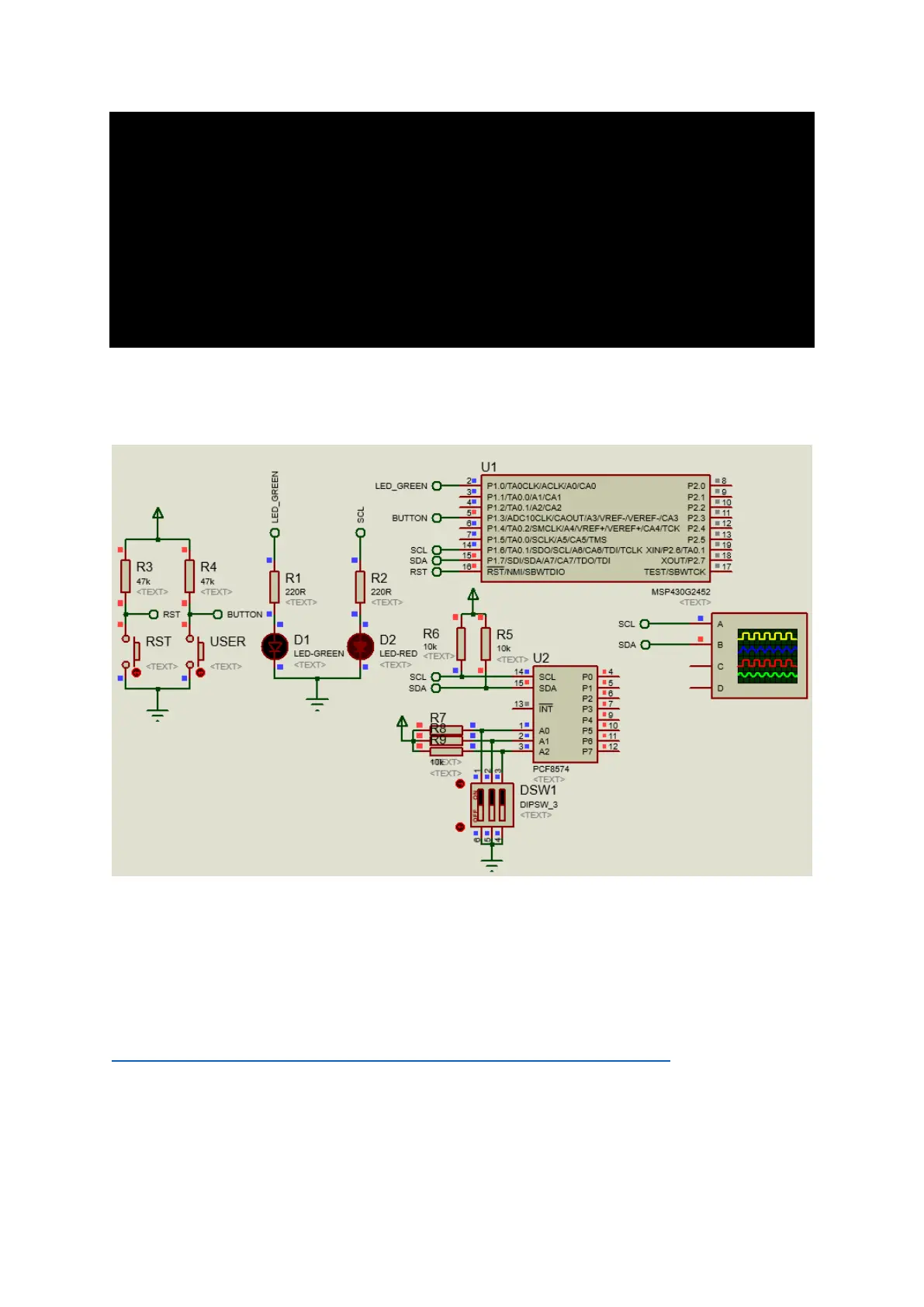
Simulation
Explanation
To keep things simple, I demoed USI-based I2C using PCF8574 8-bit I2C GPIO expander. Here the GPIOs
of PCF8574 are used to create a running LED light pattern similar to Kitt Scan from the popular series
Knight Rider. The code for USI-based I2C implementation is obtained from TI’s wiki page,
http://processors.wiki.ti.com/index.php/I2C_Communication_with_USI_Module. I did some minor
modifications on it. The code is self-explanatory with detailed documentation on the wiki page and so
I won’t be discussing it. The rest of the code is the implementation of PCF8574 driver and actual demo
code.