83
Simulation
Explanation
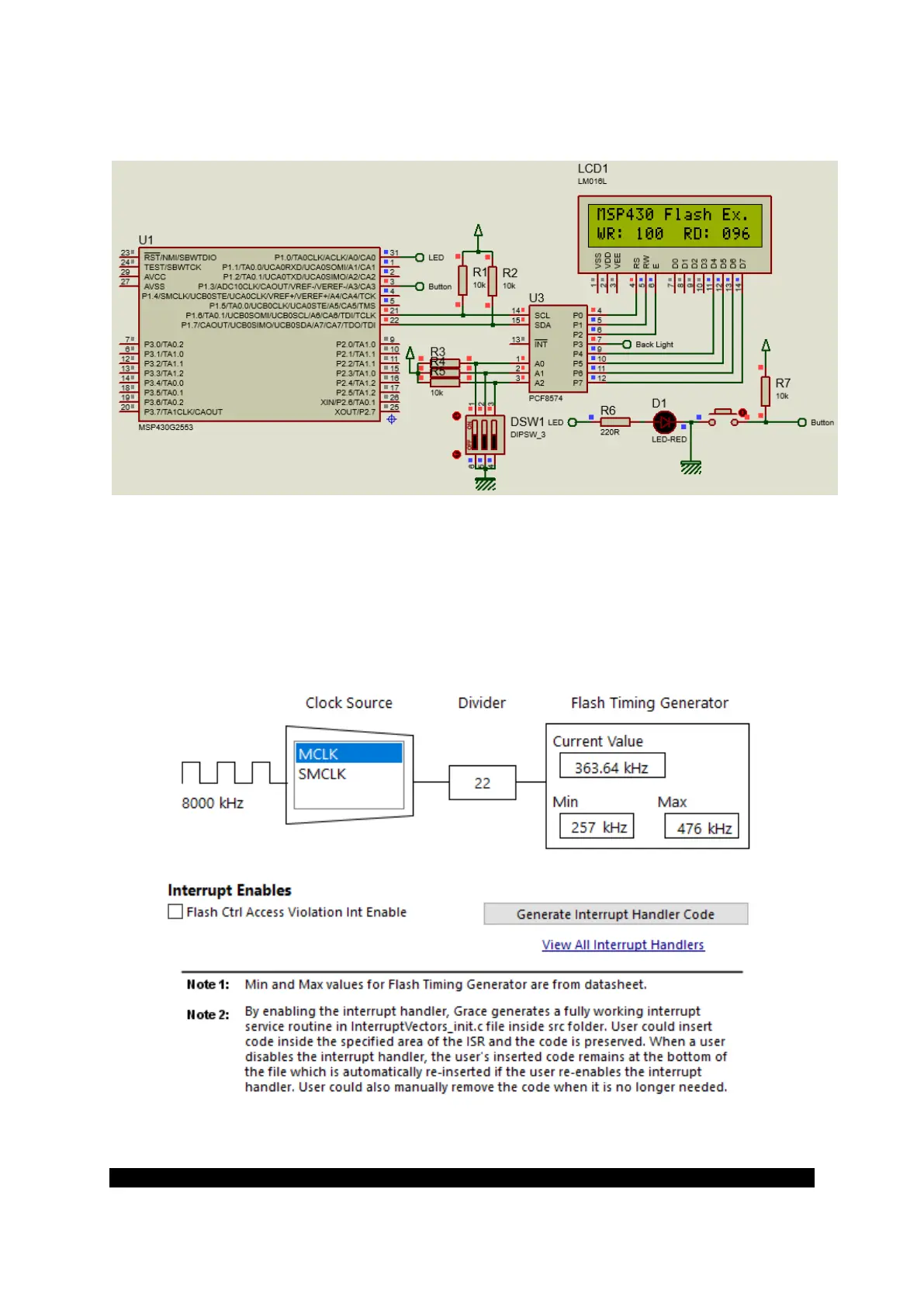
The flash memory module of MSP430s has an integrated controller that controls programming and
erase operations. The controller has four registers, a timing generator, and a voltage generator to
supply program and erase voltages.
Using Grace, we initialize the aforementioned:
FCTL2 = FWKEY | FSSEL_1 | FN4 | FN2 | FN0;