48
/* USER CODE END (section: RTC_B_graceInit_prologue) */
/*
* WDTCTL, Watchdog Timer+ Register
*
* WDTPW -- Watchdog password
* WDTHOLD -- Watchdog timer+ is stopped
* ~WDTNMIES -- NMI on rising edge
* ~WDTNMI -- Reset function
* ~WDTTMSEL -- Watchdog mode
* ~WDTCNTCL -- No action
* ~WDTSSEL -- SMCLK
* ~WDTIS0 -- Watchdog clock source bit0 disabled
* ~WDTIS1 -- Watchdog clock source bit1 disabled
*
* Note: ~<BIT> indicates that <BIT> has value zero
*/
WDTCTL = WDTPW | WDTHOLD;
/* USER CODE START (section: RTC_B_graceInit_epilogue) */
/* User code */
/* USER CODE END (section: RTC_B_graceInit_epilogue) */
}
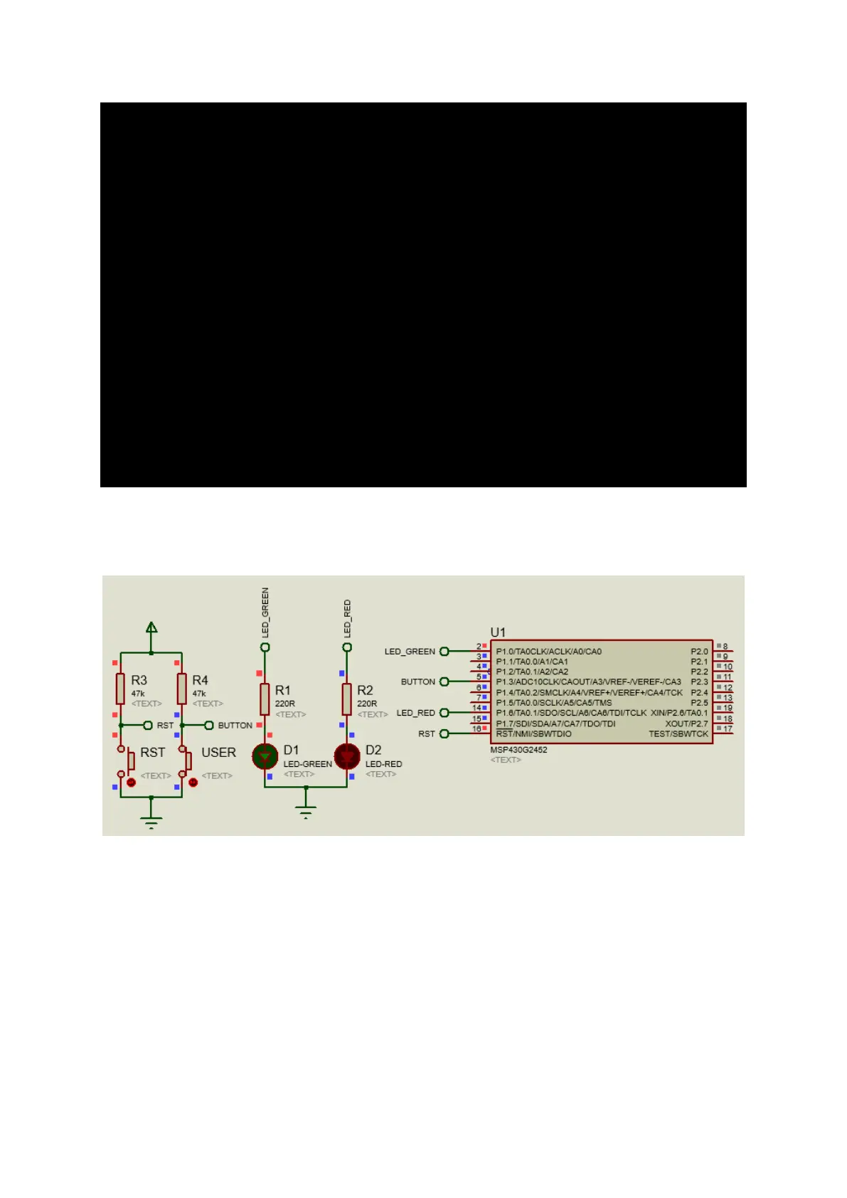
Simulation
Explanation
The most classical “Hello World” demo for digital I/Os is blinking a LED. Here I demonstrated the same
but with some minor differences. Here Launchpad board’s user button and LEDs are used. LED
connected to P1.6 blinks continuously while P1.0 LED blinks only when the user button is pressed,
slowing down P1.6 LED’s blink rate. Note _delay_cycles were used to create software delays.
At this stage I must point out, some basic rules that we must follow when we use digital I/Os of
MSP430s:
• Unused I/Os should be declared as inputs or they should be externally pulled to VDD/VSS.