44
Digital I/Os (DIO)
MSP430s, just like any micro, have digital I/Os for general-purpose input-output operations. The
resources and features of MSP430 digital I/Os are very rich and more or less comparable to a typical
ARM microcontroller. All I/O can be independently programmed. Many I/Os have external interrupt
feature. Another cool feature is the availability of both internal pull-up and pull-down resistors for all
I/Os and they can be individually and independently set. Additionally, many I/Os have alternate roles
for communication buses, clock, etc. However, the digital I/Os are not 5V tolerant and we must be
careful interfacing external devices with our MSP430 chips. I strongly recommend using some form of
logic-level conversion circuitry in such cases.
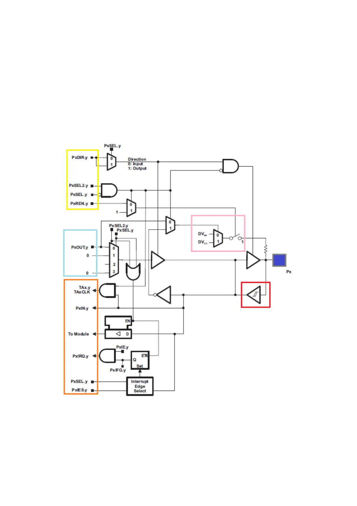
Typically, there are four major components in a digital I/O as highlighted in the block diagram above.
The yellow region is responsible for setting I/O properties, the light blue area is dedicated for output
functionalities, the orange area for inputs and external interrupts, the pink zone for internal pull
resistors and finally the red area signifying the presence of a Schmitt trigger input stage which is very
useful for noisy environments.