203
Explanation
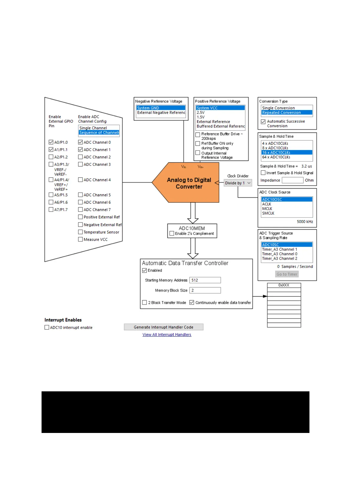
Except some minor differences, the Grace setup here is same as the one used in the DMA example.
The first difference is the Sequence of Channels selection, second is the number of ADC channels and
finally the size of memory block.
In the main, most of the things are same as in the DMA example. Since two channels are read, two
memory locations store individual ADC data. Scanning starts from topmost channel to the bottommost
and so the bottommost memory location will hold the data of the topmost channel and vice versa. In
short, the memory locations are flipped with respect to ADC channels.
ADC10CTL0 &= ~ENC;
while (ADC10CTL1 & BUSY);
ADC10CTL0 |= (ENC | ADC10SC);
lcd_print(12, 0, ADC_value[1]);
lcd_print(12, 1, ADC_value[0]);
delay_ms(400);