74
Explanation
This is a pretty straight example. The code here works by first flashing the Launchpad board’s red LED
for some time. During this time the MSP430 is running in active mode. After the flashing is over, the
MP430 micro enters LPM2 state. Note that in LPM2 state all except the DC generator and ACLK are
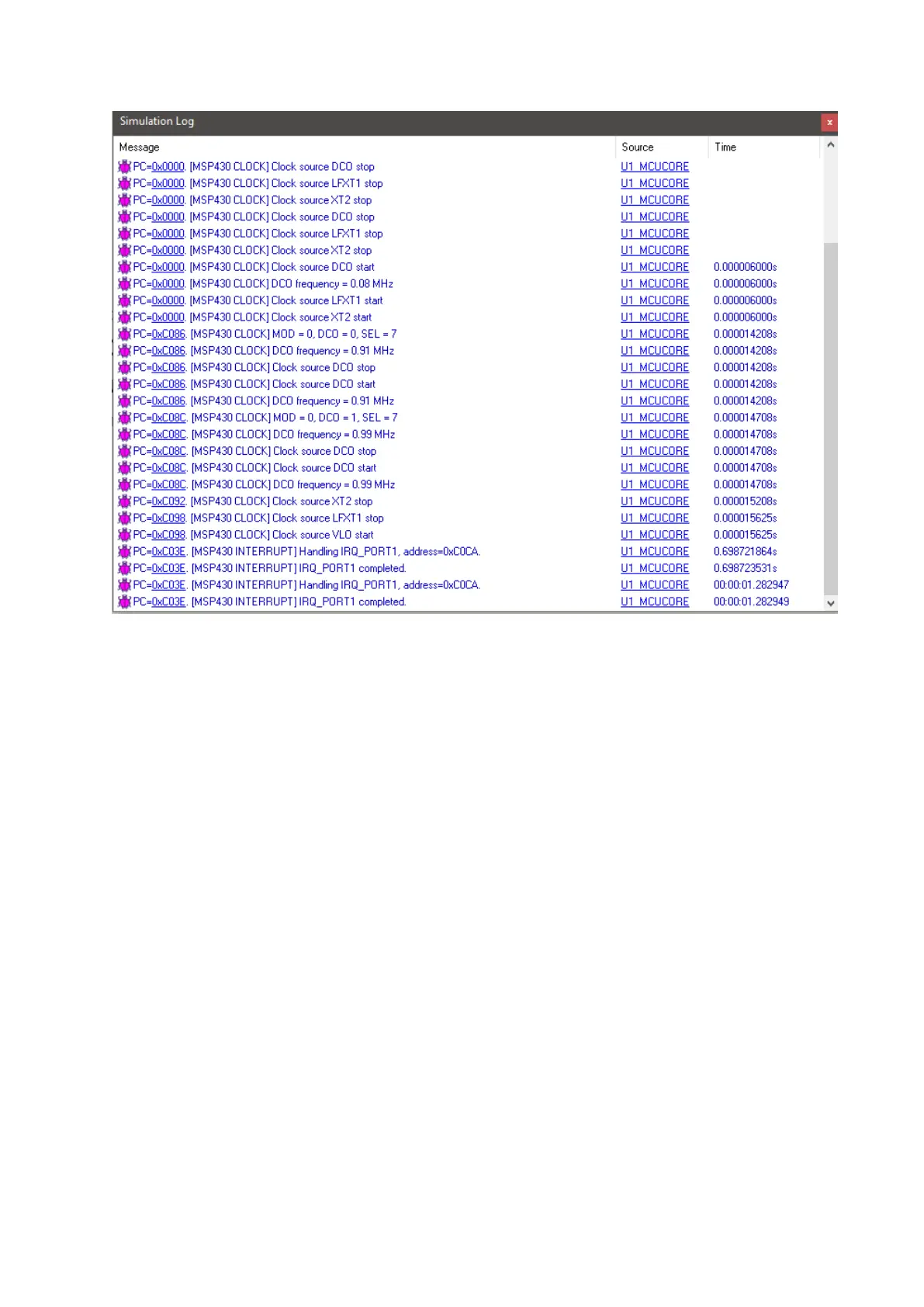
turned off. At this stage to wake up and exit LPM2, an interrupt is needed. Here this interrupt is
generated by the external interrupt caused by pressing the Launchpad board’s user button. In the
interrupt service routine (ISR), LPM2 is left and is indicated by a brief flash from the Launchpad board’s
green LED. After executing the ISR, the code returns to main function and the process repeats again.
Note that for LPMs, there is no segment in Grace and LPM code definitions can be found in device’s
header files.