174
Explanation
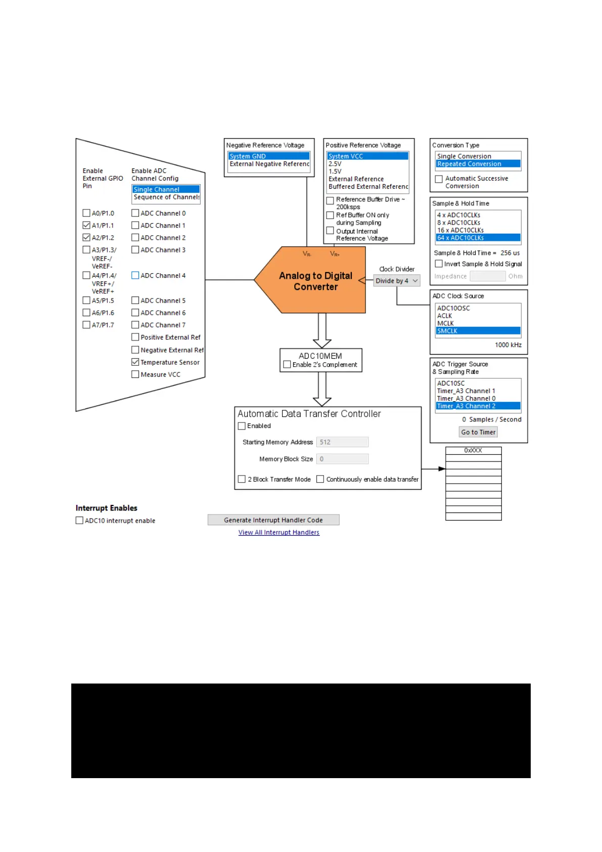
ADC10 is set up initially as depicted below:
Note that we are not using ADC10 interrupt and enabled two external channels (A1 and A2) although
only the temperature sensor channel is selected for conversion. The internal temperature sensor has
the highest channel number (channel 10) after VDD measurement channel (channel 11). If we also
want to sense A1 and A2 along with the internal temperature sensor, we have to select all channels
from channel 0 to channel 10 even when we don’t want the others. This is so because in sequence
scan mode conversion, all channels are scanned from the highest channel to channel 0. The other way
to sense only the desired channels is to sense them one at a time i.e. as single channels. The latter
method is used here.
unsigned int get_ADC(unsigned int channel)
{
P1OUT ^= BIT0;
ADC10CTL0 &= ~ENC;
ADC10CTL1 &= ~(0xF000);
ADC10CTL1 |= channel;