THRUSH AIRCRAFT, INC – MODEL S2R-G10
AIRCRAFT MAINTENANCE MANUAL
6-15
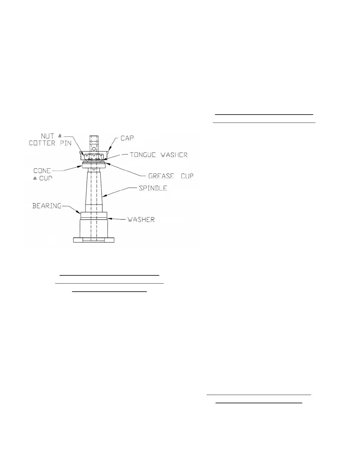
C. Remove red plastic cap plug
(dustcover).
D. Remove cotter pin, castellated nut,
tongue washer, grease cup washer,
and cone bearing.
E. Remove spindle assembly and thrust
washer from spindle housing. Do not
remove upper bearing cup or bottom
bronze bushing unless replacement is
indicated by inspection.
FIGURE 6-7: SPINDLE ASSEMBLY
CLEANING, INSPECTION AND
REPAIR OF TAIL GEAR SPINDLE
HOUSING ASSEMBLY.
A. Clean all parts with a suitable type
cleaning solvent.
B. Inspect all bolts, bearings and
bushings for excessive wear, corrosion
and damage.
C. Inspect spindle assembly for cracks,
excessive wear, corrosion and
damage.
D. Inspect spindle housing for cracks,
excessive wear, corrosion and
damage.
E. Inspect lock pin lower plate and lock
pin top plate assembly for cracks,
corrosion and damage.
F. Repair of tail gear sub-assembly is
limited to reconditioning of parts such
as replacing bearings and bushings,
smoothing out minor nicks and
scratches, repainting chipped or
peeled areas and replacement of
component parts.
TAIL GEAR WHEEL AND TIRE
REMOVAL AND DISASSEMBLY
Ref. figure 6-8
To remove and disassemble tailwheel &
tire, proceed as follows.
A. Using a suitable Jack. Jack and
secure tail of aircraft at tailwheel
trunnion jackpoint.
B. Deflate tire by depressing the schrader
valve stem plunger until air can no
longer be heard escaping from the tire.
C. Remove schrader valve core.
D. Remove cotter pin and through bolt
castellated nut. Remove the through
bolt, cut the safety wire to collar nut
and remove the wheel and axle.
Unscrew the collar nut and remove the
axel from the wheel.
E. From each side of wheel; carefully
remove snap ring, felt grease seal
retainer, felt grease seal, grease seal
ring and cone bearing. Store the cone
bearings. Label the bearings for
reinstallation into position from which it
was removed.
F. With the tire completely deflated,
removing the wheel through-bolts will
separate the wheel halves. Pull the
wheel halves from the tire by removing
the wheel half opposite the valve stem
first. Mark wheel halves to note
relationship to each other for
reassembly.
INSPECTION OF TAIL LANDING
GEAR WHEEL ASSEMBLY
A. Visually check all parts for cracks,
corrosion, distortion, defects and
excessive wear.
Effective: 03/26/2010 Page