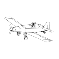
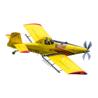
THRUSH AIRCRAFT INC - MODEL S2R-G10
AIRPLANE MAINTENANCE MANUAL
PROPELLER DESCRIPTION AND
OPERATION
The propeller is a single-acting unit in
which hydraulic pressure opposes the
forces of springs and counterweights to
obtain the correct pitch for engine load.
Hydraulic pressure urges blades toward
low pitch (increasing rpm), while springs
and counterweights urge blades toward
high pitch (decreasing rpm). See the
propeller owner’s manual for more explicit
details.
The source of hydraulic pressure for
operation is oil from the engine lubricating
system, boosted in pressure by the
governor gear pump, and supplied to the
propeller piston through the beta tube
(beta tube supplied by engine
manufacturer). The flow of oil through the
governor and the propeller does not
interfere with engine lubrication.
The propeller is designed to operate in two
modes of operation – governor mode and
beta mode.
Governor mode
. Oil is metered to and
from the propeller (by the governor control
valve as positioned by flyweights),
increasing and decreasing blade angle
(changing pitch) as required when the
propeller speed control setting is altered,
or to control and stabilize engine speed
with varying power conditions or flight
altitudes with a fixed speed setting.
Beta mode. The pilot may select beta
mode for ground reversing or taxi
operation. In the beta mode, the
aircraft/engine mechanical linkage
repositions a sleeve on the beta tube to
allow high pressure oil to reach the
propeller piston and move the blades
toward reverse pitch. In beta mode the
engine automatically, by controlling fuel
flow, develops power output to correspond
with the pitch setting (determined by the
pilot).
Cockpit procedure for normal constant
speed operation, starting, stopping and
ground run-up is consistent with standard
practice for this type propeller.
In-flight loss of oil pressure, whether due to
system failure or pilot manipulation of the
feather control, will cause the blades to
move to the feathered position. The
electric, hydraulic, unfeathering pump is
required to un-feather the propeller.
The propeller hub cavity is partially filled
with turbine oil which is sealed in the hub
and isolated from engine oil. This oil
provides lubrication and corrosion
protection to blade bearings and other
internal parts.
The propeller is equipped with a start lock
mechanism which prevents the blades
from going to full feather on engine shut-
down. The mechanism operates in
response to the centrifugal force acting on
rotating weights. The mechanism is
designed to engage a fixed stop and limit
piston movement in the direction of
increasing blade angle during engine shut-
down. During all flight operations, the
weights are in a disengaged position and
offer no resistance to feathering,
Unfeathering or reversing of the propeller.
PROPELLER REMOVAL –
McCauley
Remove upper half of nose bowl.
Remove spinner and spinner fillets. Mark
location of parts. (Note number of shims
under the plastic spinner support.)
Remove beta tube retainer plug assembly
and beta tube.
* NOTE *
Beta tube retainer plug cannot be
removed with McCauley propeller in
feathered position. Remove plug
assembly with propeller on start
locks.
4-5
* NOTE *
Effective: 03/26/2010 Page