THRUSH AIRCRAFT INC - MODEL S2R-G10
AIRPLANE MAINTENANCE MANUAL
RIGGING INSTRUCTIONS
a. Rigging the throttle quadrant to the
control cables: Ref. Fig. 4-3
1. With clevis forks (2 places) not yet
connected to levers, turn the
AN315-4 check nut in to bottom
out on the cable-end threads.
2. Screw the clevis fork out until the
witness holes is just covered
enough to prevent passage of
.032 diameter safety wire.
3. Count the number of threads
exposed between the fork and the
check nut. Screw the fork in one
half way toward the check nut.
4. Run the check nut up to meet the
fork and install the forks in bottom
holes as shown. Do not tighten
nut or install cotter pin at this time.
b. Rigging the control cables to the
19305-21 bracket:
1. Set the control cable assembly (2
places) so that an equal amount
of threads are in either side of the
bracket. Tighten nuts equally so
that grease (Zerk) fittings on fwd
side of bracket are accessible for
maintenance.
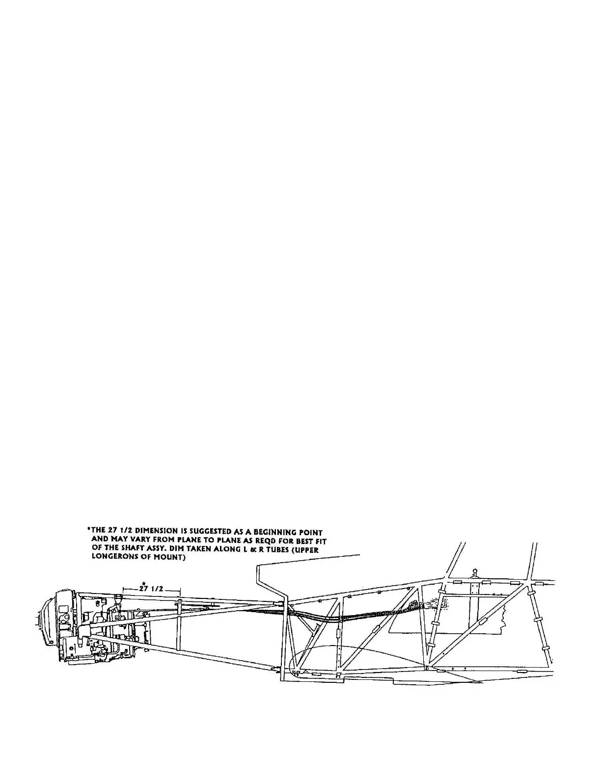
c. Positioning the 21712-1 control shaft
assembly on the airframe:
1. Refer to Fig 4-4 for this
dimension.
d. Rigging the emergency cutoff/manual
feather lever to the control cable:
1. Repeat steps 1. thru 4. in throttle
quadrant instructions (above), and
install cotter pin and tighten cable
nuts with equal threads showing
on both sides where the cable
housing passes through the
bracket on the assembly. NOTE:
This control has only one hole at
the bottom of the lever.
e. Rigging the engine to the control shaft
assembly, P/N 21712-1:
* NOTE *
This procedure assumes that the
engine linkages (Garrett/Honeywell
supplied) have already been rigged
per Honeywell Engine Maintenance
Manual. If not, do so at this time.
After completing, proceed as
follows:
Figure 4-4:
Page Effective: 03/26/2010 4-12