THRUSH AIRCRAFT, INC – MODEL S2R-G10
AIRCRAFT MAINTENANCE MANUAL
D. Install left and right elevator using P/N
40065-1 spacer, AN4-12A bolt and
AN4-11A bolts in center and outboard
hinges. Connect elevator control arm
and check travel 27 ±1 up and
17±1 down.
E. Connect elevator trims tabs and check
for proper travel.
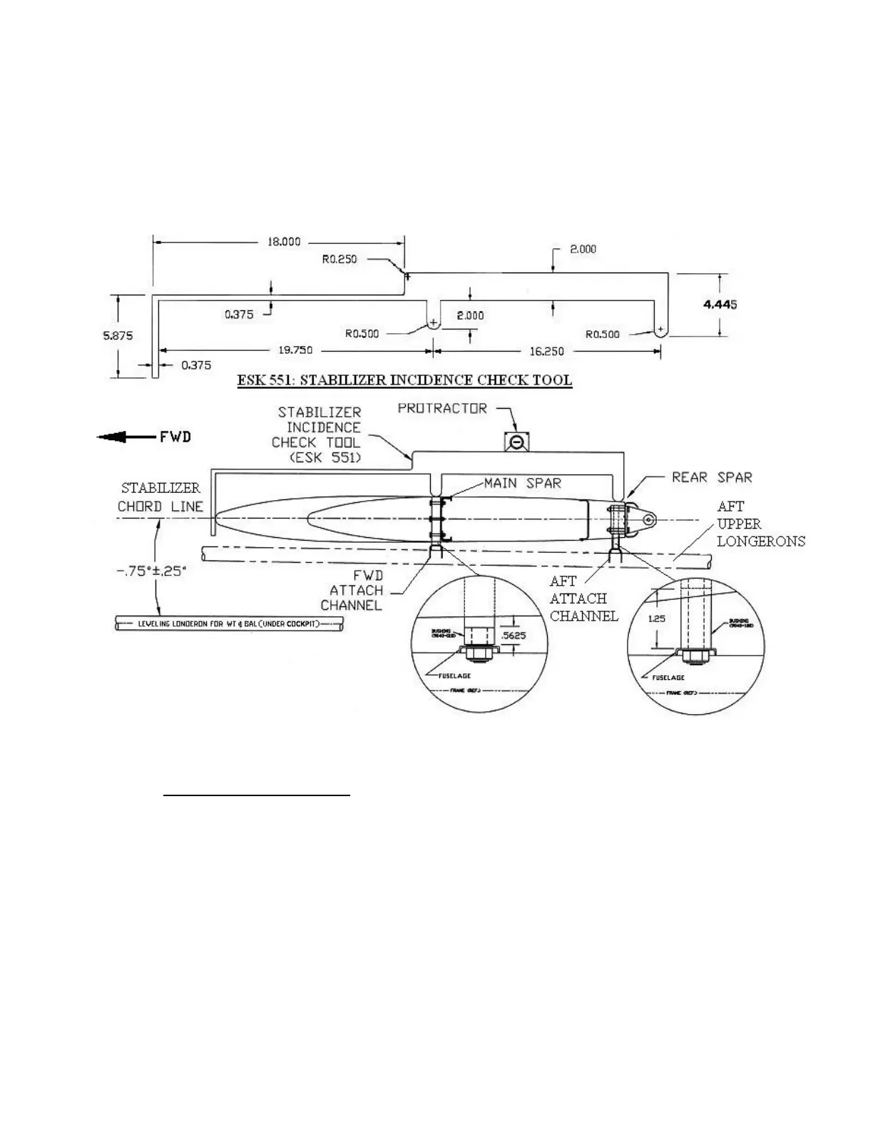
Figure 7-10: Stabilizer Attachment to Fuselage
VERTICAL STABILIZER
A. Install forward attachment loosely
with NAS6207-68 bolt. Using either
no shims (normal) or, if a gap exist,
use one or more of the following P/N
21209T001 (.125”) and/or P/N
21209T002 (.250”) shim(s) at upper
attach and P/N 21208T001 (.125”)
and/or P/N 21208T002 (250”)
shim(s) at lower attach. Install
hardware upper and lower and
navigation light ground wire (lower
attach); tighten all vertical fin
hardware per torque table (See
Figure 2-7). Using a string pulled tight
through upper rudder hinge and lower
rudder hinge, check hinges for
alignment fore, aft, left and right. It is
permissible to add (1) P/N 40207T005
(.050”) or 40207T007 (.063”) shim
between the center hinge bearing
housing and vertical fin rear spar to
achieve proper alignment.
Effective: 03/26/2010 Page 7-17