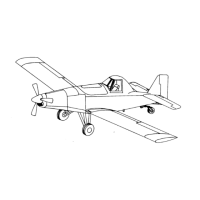
THRUSH AIRCRAFT INC – MODEL S2R-G10
AIRCRAFT MAINTENANCE MANUAL
Page 8-2 Effective: 03/26/2010
INSTRUMENTS
GENERAL DESCRIPTION
The standard instruments are located on
three panels in the cockpit. An upper
panel, a left lower panel, and a right
lower panel. The left lower panel
contains an oil temperature gauge, oil
pressure gauge, fuel pressure gauge,
hour meter, airframe related electrical
switches and the fuel quantity gauge. A
clock is optional. The right lower panel
contains the voltmeter, ammeter, and
circuit breakers. The upper instrument
panel contains the manifold pressure
gauge, tachometer, air speed indicator,
altimeter, “wet” compass, stall warning
light and turn coordinator. If the airplane
is certified for night flight, all instruments
are lighted with a post light or internally
lighted and controlled with rheostats
located on the left lower panel.
Optional instruments and gauges are
available upon request. A few of the
optional instruments are hopper
quantity, Micronair™ chemical flow
meter, Crophawk™ chemical flow
meter, encoding altimeter, artificial
horizon, electric turn and bank, vertical
speed, and directional gyro.
INSTRUMENT SYSTEM
MAINTENANCE
Unless otherwise specified, field
maintenance of instrument systems is
limited to removal and replacement of
defective instruments and transmitters;
authorized in-service adjustment of
transmitters and instruments; and repair
of instrument systems between the
instrument and signal source
(transducer). Reliability of the various
instruments and related systems can be
sustained by routine inspection of
electrical wiring for chafing and electrical
connections for security. All fluid pressure,
pitot pressure, and static line connections
must be tight at all times and lines must be
correctly routed and secured. Electrical
wiring must be free from chafing, properly
connected and secured. Instrument ports
and lines disconnected during system
maintenance must be capped or plugged
immediately to prevent the entrance of
foreign material and consequent instrument
malfunction. Maintenance procedures
pertaining to a specific instrument or
system are contained in subsequent
sections. As a general rule, it is
recommended that the instrument signal
source and means of transmission to the
instrument be inspected and functionally
checked before changing an instrument. If
a new instrument or a transducer is
available, it may be expedient to utilize
them in the system to determine if the
malfunction is in the instrument, signal
source or interconnecting line.
FLIGHT INSTRUMENTS
Ref. Figure 8-1, 8-2, 8-3 & 8-4
Flight instruments consist of the magnetic
compass, airspeed indicator, altimeter and
turn coordinator. The pitot-static system
provides pitot (dynamic) and static
(atmospheric) air pressure to the airspeed
indicator and static air pressure to the
altimeter.
PITOT-STATIC SYSTEM
The pitot head is installed on the right wing
lower surface outboard of the tie-down ring
and provides pitot pressure. A heated pitot
head is available as an option. The pitot
pressure line is routed to the forward side of
the wing main spar and then inboard
through the root rib. It is then routed up to
the fuel vent line, across to the left side of
the fuselage, and then aft to the cockpit.
The static pressure ports are located on
both sides of the aft fuselage and are