THRUSH AIRCRAFT, INC – MODEL S2R-G10
AIRCRAFT MAINTENANCE MANUAL
6-17
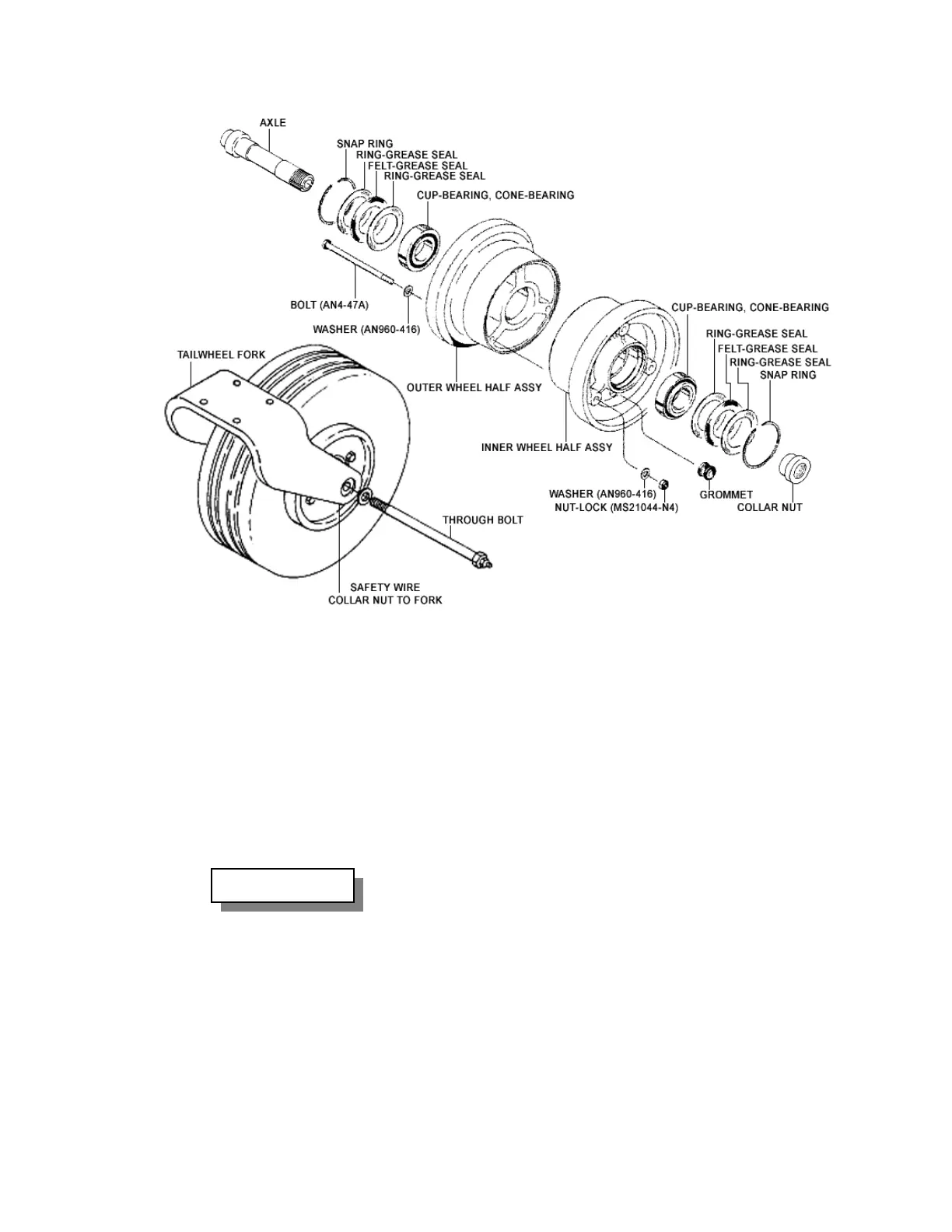
FIGURE 6-8: TAIL LANDING GEAR WHEEL ASSEMBLY (FORK TYPE)
NOTE *
Tires and tubes are balanced as
individual units and marked at
time of manufacture. The tire
balance mark is a red dot. The
tube balance mark is a yellow
stripe on the base of the tube.
Always assemble tire and tube
with marks aligned.
Uneven or improper torque
may cause a bolt or wheel
failure. Inflate tire until tire
beads are sealed, remove
schrader valve core, and
allow tube to completely
deflate. Install the valve-core
and inflate 12.5x4.5 10pr tire
to 55 psi max. Assure
schrader valve does not leak
before replacing valve cap.
D. Install tire and tube on the wheel half
containing the valve stem hole and
then the opposite wheel half.
E. Install the wheel through-bolts with bolt
heads opposite valve stem side,
tighten nuts evenly and torque to 90
inch-pounds.
F. Repack bearing cones with MIL-G-
81322 (Aeroshell 22) grease or
equivalent.
WARNING!
G.
On each side of wheel; apply a thin
coating of grease on bearing cups,
install freshly repacked bearing cones,
install grease seal ring, felt grease seal
and another grease ring seal. Note:
Lightly fill grease seal felts with SAE
10wt Oil (3-in-ONE oil) (do not soak),
and carefully install snap ring. Install
the two (2) P/N95435-11 spacers, one
on each side of wheel assembly.
H. Inspect tail wheel axle for anomalies,
then apply a light coating of grease.
Effective: 03/26/2010 Page