TD80™ Level Gauging and Overfill Prevention System Product Manual
Page 116 TD80 Operation/ Rev. 2, August 4, 2015
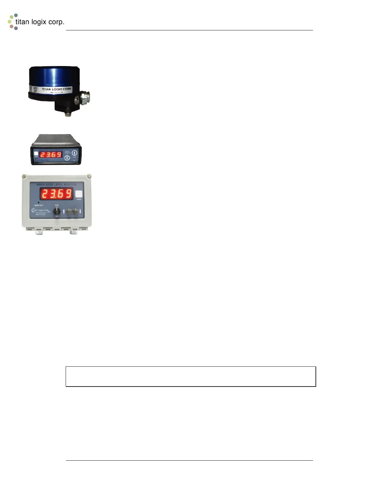
5.1 TD80 System Components
TD80 Transmitter
The TD80 transmitter generates and processes the Guided Wave Radar
signals to determine liquid level in a tank. The TD80 is mounted on the tank
top and connected to the probe, is weatherproof and rated for use in
hazardous locations where explosive fumes may be present. TD80s are
available in two versions, dual rod or coaxial probe for compatibility with a
wide range of liquids.
Probe
The probe guides the transmitted pulse and reflection from the surface of the
liquid. Probes are available in dual rod or coaxial versions and require a
matching transmitter type. The probe is mounted on the tank top and is
connected to the bottom of the transmitter. Dual rod probes are designed for
viscous liquids. Coaxial probes are used mostly for tanks containing products
like aviation fuel.
Finch 5332 Display
Finch Displays are available in weather-proof external versions, the Finch
5332E and a smaller internal version, the Finch 5332. Both provide bright
LED numeric display of volume information, alarms and system error codes
from the TD80 transmitter. Various alarm and error conditions are detected
by the transmitter and display. These alarm states control three internal
relays for alarm annunciation, overfill and low level prevention.
Start Up
When power is applied to the Finch display and TD80 transmitter, the TD80 will run
through a 10 second, warm-up cycle. During the TD80’s warm-up cycle the Finch Display
will run its own tests, during which the Finch display will show the current software
revision number, followed by a display test consisting of all four digits showing the values
from 0 to 9 and A to F. At the same time as the display test, the unit will test the Fill and
Spill/Fail relays. The unit will wait 2 seconds, pulse the Fill relay for 1 second, wait for 2
seconds, and pulse the Spill/Fail relay for 1 second.
The operator can set the unit into calibration mode, by pressing and holding either of the
front panel buttons while turning the power on. If no button is pressed the unit will enter
its normal mode of operation (either Monitor Mode or Off Mode depending on the Gauge
or Display Enable signal controlled by the PTO).
Note: If the display test is completed before the transmitter warm-up; the unit will display
four dashes (----) for a few seconds while the transmitter warm-up completes.
5.2 Introduction to Operation
The TD80 continuously measures liquid level in the tank and transmits volume
information with alarm states to the Finch display. This information is presented on a
large 4 digit display and is transmitted to alarm controlled relays. The alarms and any
errors are clearly displayed for operator intervention as flashing messages on the Finch
display. Alarms and errors also control three separate relays that signal or control
external devices.

 Loading...