TD80™ Level Gauging and Overfill Prevention System Product Manual
Page 146 TD80 Programming/ Rev. 2, August 4, 2015
6.3.5 Connecting the TD80 for Programming Using the SVRS232
to USB Converter
6.3.5.1 Connecting the TD80 for Programming in the Shop
See Figure 6-1 and Figure 6-2 for details.
1. Connect port “A” to the SVBus Converter.
2. Connect contact “B” to contact “C”.
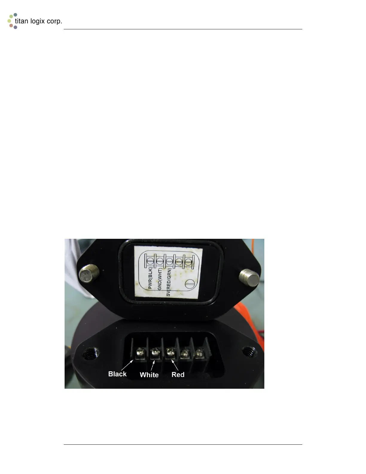
3. Clip the SVBus Converter alligator clips to the transmitter terminals or to the same
colour wires of the attached TD80 cable kit. See the wiring compartment cover diagram
for the terminal locations.
a. Black clip to PWR(BLK) terminal
b. White clip to GND(WHT) terminal
c. Red clip to SV(RED/GRN) terminal
4. Connect the SVBus converter to the PC USB port.
5. Connect the AC power adapter to the SVBus converter. Caution, do not connect the
AC power adapter if using a battery or other source of power.
6. Apply operating power when prompted by the Birdfeeder program.
Figure 6-1: Connecting the TD80 for Programming in the Shop

 Loading...