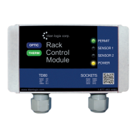
TD80™ Level Gauging and Overfill Prevention System Product Manual
Rev. 2, August 4, 2015/ TD80 Installation Page 45
2.6 TD80 Basic Alarm Installation Wiring
The TD80 and Finch Display generated alarms are available for controlling a variety of
lights, horns, solenoid operated valves and other devices. These alarms control three
sets of dry contact relay outputs. The suggested alarm wiring below is for a basic system
of lights or horns to alert an operator for further action.
2.6.1 Finch 5332E/PS, Red Terminal Board Wiring Instructions
Wiring steps for a single TD80 and Finch Display. Refer to Figure 2-17 for Finch
5332E/PS (red board) installation. The alarm relay contacts are rated for 30VDC, 2A
continuous current maximum. Each set of contacts is protected by a 2A fuse located on
the terminal board.
Ensure that the power and ground are connected as described below.
1. Fused Power wire from nose box socket or junction box to Finch POWER IN (25)
2. Ground wire from nose box socket or junction box to Finch GROUND IN (24)
Fill/Fall Alarm Installation
1. Finch FILL-COM (12) to POWER OUT (14)
2. Horn or light to Finch FILL-NO (10) and Electrical Ground
3. Finch Jumpers, see Figure 2-37
a. J1 to “B” position
b. J9 removed for Fill alarm, installed for Fall alarm
High-High (HH) Alarm Installation
1. Finch HH-COM (17) to POWER OUT (19)
2. Horn or light to Finch HH-NO (15) and Electrical Ground
Spill/Fail Alarm Installation
1. Finch SPILL/FAIL-COM (21) to POWER OUT (23)
2. Horn or light to Finch SPILL/FAIL OUTPUT (20) and Electrical Ground
3. Finch Jumper J10 to “A” position, see Figure 2-37
NOTE: Once the Basic Alarm Installation Wiring is complete, refer back to section 2.1.2,
TD80 Installation Steps Overview, for clarification on the next installation step.
2.6.2 Finch 5332E, Green Terminal Board Wiring Instructions
Wiring steps for a single TD80 and Finch Display. Refer to Figure 2-18 for Finch 5332E
(green board) installation. The alarm relay contacts are rated for 30VDC, 2A continuous
current maximum.
Ensure that the power and ground are connected as described below.
1. Fused Power wire from the nose box socket or junction box through a 3A fuse to
Finch 8-28 VDC POWER
2. Ground wire from nose box socket or junction box to Finch GROUND
Fill/Fall Alarm Installation
1. Finch FILL-COM to 8-28VDC POWER

 Loading...