TD80™ Level Gauging and Overfill Prevention System Product Manual
Rev. 2, August 4, 2015/ TD80 Installation Page 49
2.7 TD80 Overfill Prevention System Installation Wiring
2.7.1 Finch Relay Module Installation Wiring
The TD80 generated alarms, through the Finch Display control the optional Finch Relay
Module for onboard overfill prevention. The loading process may be controlled by a
bottom loading valve or bypass of a hydraulic motor powered pump. A single, normally
open (NO), high current relay contact powers an external device to enable loading; while
removal of the power disables loading as a failsafe control method.
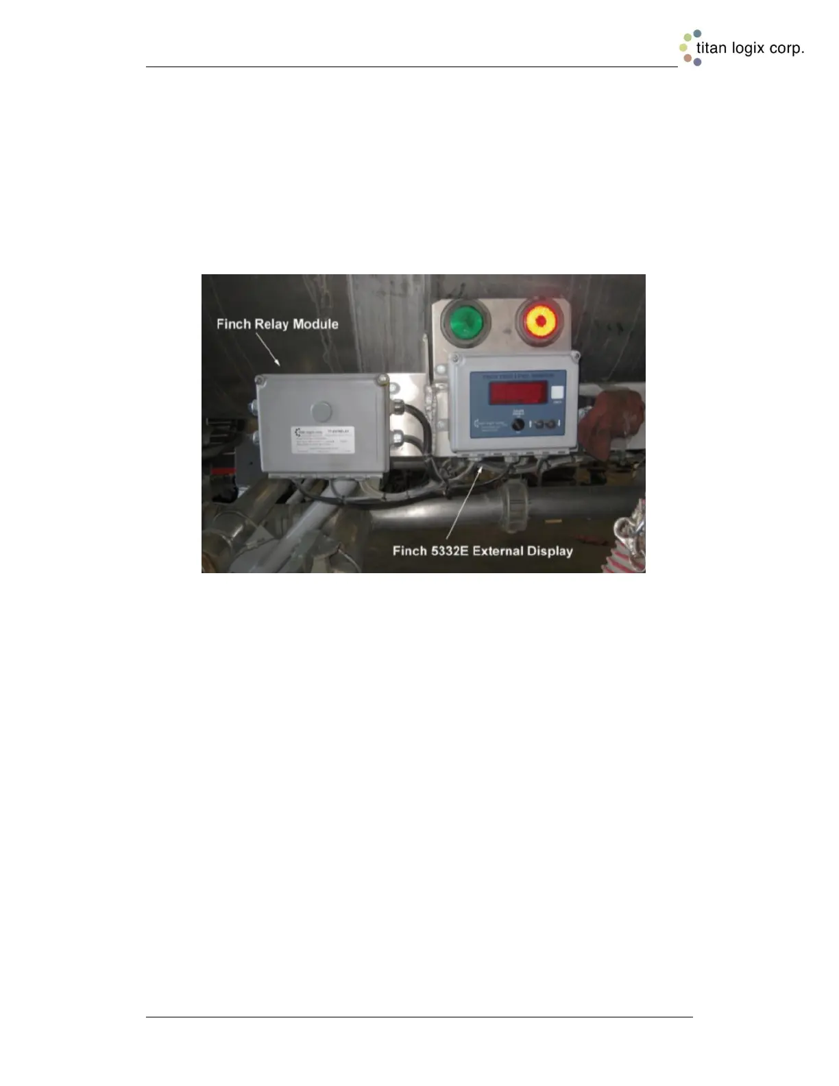
Figure 2-19: Overfill Prevention Installation Example
The wiring steps described below use the recommended TD80 transmitter, Finch Display
and Finch Relay Module.
The most common control devices for overfill prevention are:
1. A normally closed (NC) bottom loading valve
OR
2. A normally open (NO) hydraulic motor bypass valve
Install the Finch Relay Module in a Non-Hazardous location only.
Finch 5332E/PS, Red Terminal Board Wiring Instructions
Wiring steps for a single TD80, Finch Display and Relay Module. Refer to Figure 2-20,
Figure 2-25 & Figure 2-26 for Finch 5332E/PS (red board) installation.
Note that the horn, red and green lights are optional accessories. The PTO signal must
be connected to the Finch Display mounted Gauge Enable switch or to a switch
controlled by the PTO or air brake. Power may be controlled by the optional brake air
switch.
1. Fused Power and Ground wires from nose box socket or junction box through a 5A
fuse to Relay Module POWER (15) and GROUND (14)
2. Optional PTO or brake air switch to Relay Module PTO (13) and Electrical Ground
3. Relay Module GAUGE GND (2) to Finch GROUND IN (24)

 Loading...