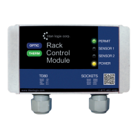
TD80™ Level Gauging and Overfill Prevention System Product Manual
Page 72 TD80 and Overfill Prevention System Troubleshooting/ Rev. 2, August 4, 2015
The test light may also be used to bridge a wire break. It is current limited and will
indicate current flow in the circuit. The internal resistance of the light bulb will allow some
circuit components to operate such as horns, relays and lights. It will not provide
operating power for a full system and indicates low current with a dim light.
4. Short circuit isolation
This can be done by disconnecting the devices from the affected wire or signal, then
testing at each circuit point until the short circuit or defective component is isolated.
1. Short circuit to ground isolation.
a. Disconnect the shorted wire at each component to isolate the short circuit.
b. Clip on battery power; probe each component at the shorted terminal and
disconnected wire. A short circuit to ground is indicated by the light partially
or fully illuminating.
2. Short Circuit to power isolation.
a. Disconnect the shorted wire at each component to isolate the short circuit.
b. Clip on ground; probe each component at the shorted terminal and
disconnected wire. A short circuit to power is indicated by the light partially or
fully illuminating.
3.2 TD80 System Specific Troubleshooting
Specific parts of the TD80 and Overfill Prevention System are tested using a combination
of voltage checking and power/ground applied with the test light. The test light does not
precisely measure the circuit voltage and is not a completely short circuit for applying
voltage or ground. This must be kept in-mind during the troubleshooting process.
Troubleshooting a TD80 system is as uncomplicated as looking for circuit power and
grounds. A circuit point is either properly connected to battery power or ground through
wiring or devices controlled by the TD80; or not. Finding the defective component is
troubleshooting or sometimes described as fault isolation. Once the defective component
is determined, it is replaced or repaired and the system is fully tested to confirm correct
operation. It is common for more than one defective component to cause a system
failure.
3.2.1 Common System Wiring and Component Failures Overview:
1. Loss of power. No system operation, Finch Display is blank.
2. Finch Display shows “OFF” when the PTO is engaged or Gauge Enable is on.
3. Loss of SV Bus Communication, Finch Display shows “----”.
4. Finch Display shows only a decimal point, no numbers.
5. Finch Display shows “8888” or flickers between “8888” and other numbers.
6. Finch Display restarts at erratic intervals. The digit test begins and then displays a
level for some time, then restarts with the digit test.
7. Fill Alarm remains inactive.
8. Fill Alarm continuously active.
9. Overfill Prevention System fails to allow loading.
10. Overfill Prevention System fails to stop loading on high level alarms.
11. Overfill Prevention System fails to stop loading when PTO signal is off.
12. Finch Display shows an Error Code (E xx)
13. Finch Display continuously shows “2 LO”.
14. Finch Display shows erratic level measurements or “2 LO”.
15. Spill alarm is on continuously, unable to clear the alarm by unloading while the TD80
is turned on or by entering Calibration mode.
16. Unable to offset calibrate the TD80.

 Loading...