TD80â„¢ Level Gauging and Overfill Prevention System Product Manual
Rev. 2, August 4, 2015/ TD80 Introduction Page 9
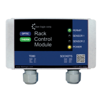
Relay Module
A Finch Relay Module is available to combine the Finch Spill/Fail and High-
High alarm relays with a signal from the vehicle mounted Power Take-Off
(PTO) to safely control an onboard overfill prevention system. The Relay
Module contains high current relays to energize a bottom loading valve or
hydraulic motor bypass valve for loading control. It also contains a terminal
strip for power and alarm accessory interconnections.
P2000
The P2000 is an accessory that enables secondary overfill prevention when
used with industry standard optic loading rack controllers. The Finch
controlled alarms provide an intrinsically safe signal to the P2000 that
permits or denies loading at the rack. The loading rack connections are
made through a standard 7-pin or 10-pin optic socket.
MIC 10
The MIC 10 is an interface device for connecting multiple TD80s to a third
party modem. Level, alarm and error information from the TD80s is collected
by the MIC 10 and forwarded to the modem. The modem is then able to
wirelessly transmit data to the back office for asset management and
tracking purposes.
It can be set to automatically transmit TD80 data at intervals based on a user
preferred configuration, or else can send data on command from the modem.
The MIC 10 features a PTO signal input to enable data transmission only
when the PTO is engaged. This limits the data bandwidth required by a
wireless modem.
1.3.5 The TD80 Alarm System
This description refers to TD80 transmitters and Finch 5332E/PS Display
(Red Terminal Board version). See notes in parentheses for the Finch 5332E
Display (Green Terminal Board version). Internal Finch 5332 description is
the same as the 5332E version. Internal Displays are connected by a pigtail
with labeled wires instead of a terminal board as in the external Finch
versions.
The TD80 alarms are listed below. A vehicle mounted Power Take Off (PTO)
unit may signal a loading or unloading event when alarms are required to be
activated. A Display Enable (PTO) (or Gauge Enable (PTO) on 5332E
Displays) signal to the Finch Display enables these alarms. An inactive PTO
signal holds all alarms in the non-alarming state to prevent false triggering
due to sloshing while driving. This PTO signal is usually a dry contact switch
closed by the mechanical engagement of the PTO.