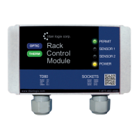
TD80™ Level Gauging and Overfill Prevention System Product Manual
Rev. 2, August 4, 2015/ TD80 Installation Page 21
i. Display shows blinking “HH” and volume
ii. Installed light and horn activate
iii. Installed overfill prevention system activates
g. HH alarm deactivates when Up-Up-Down-Up button combination is pressed.
i. Display returns to normal, not blinking
ii. Installed light and horn deactivate
iii. Installed overfill prevention system deactivates
h. Spill/Fail alarm activates when the tank level reaches the Spill alarm setting.
i. Display shows flashing “SPill”
ii. Installed light and horn activate
iii. Installed overfill prevention system activates
i. Spill/Fail alarm deactivates when the tank level decreases more than 2” below
the Spill alarm setting.
i. Display returns to normal, not flashing “SPill”
ii. Installed light and horn deactivate
iii. Installed overfill prevention system deactivates
7. Test the 4-20mA output (if installed) by doing the following:
a. Monitor the 4-20mA signal with a Digital Multimeter (DMM).
b. Short the probe with a small metal rod at several points along the length of the
probe.
c. No short across the probe produces a signal of 4mA or slightly greater.
Increasing height of the short produces an increasing current toward 20mA.
2.2.3 Offset Calibration Methods
Offset Calibration Description
Offset calibration of the TD80 transmitter is required after installation, programming or
replacement of the TD80 transmitter. The calibration compensates for variations from the
calibration chart provided by the tank manufacturer and probe mounting height above the
tank top. It is recommended to recalibrate seasonally to maintain the rated accuracy.
Small differences in tank height, probe position on the tank and variation from the
calibration chart are compensated by adjusting the displayed volume to a known amount.
Large changes to the offset calibration indicate an error in programming. Review the
calibration chart and mounting details, confirm that the TD80 transmitter is programmed
for the compartment it is installed on and reprogram if necessary.
Offset calibration will halt if the adjusted level causes the High-High alarm setting to
exceed the Spill alarm level. The High-High alarm is programmed to be no closer than ½”
below the Spill alarm. This is also an indication of incorrect programming to be resolved.
The adjusted level may only be lowered by the distance between the High-High and Spill
alarm levels.
Methods
Methods 1 and 2 are preferred, while method 3 is acceptable as better than no
calibration. The first two methods calibrate to a metered load under normal conditions.
This is the most accurate compensation for mounting location and calibration chart
differences. The third method compensates for mounting height only and does not have
any effect on variations from the calibration chart supplied by the tank manufacturer.