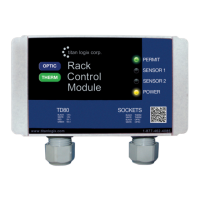
TD80™ Level Gauging and Overfill Prevention System Product Manual
Rev. 2, August 4, 2015/ TD80 and Overfill Prevention System Troubleshooting Page 71
3 TD80 and Overfill Prevention System Troubleshooting
Equipment Required:
1. Automotive Test light, 6VDC to 24VDC
2. Short length of wire bare at both ends or with alligator clips.
Optional Equipment:
1. Digital Multimeter (DMM)
2. Scully Universal Truck Tester for P2000 installations.
3.1 Overview and General Techniques
The test light is a multi-purpose tool for checking the presence of power or ground in an
automotive electrical circuit. The tip is usually pointed and sharp enough to pierce the
insulation of a wire for circuit testing. Most test lights have a low resistance path due to
the cold resistance of the light bulb. This makes it useful to apply either power or ground
to a part of the circuit. Short circuit current is limited by the light bulb to several hundred
milliamps in a typical automotive circuit. Care must be taken because even this low
current may damage some low power electronic devices. The value of a test light is its
inexpensiveness, ruggedness, ease of use and indications are readily apparent at a
glance.
1. Check presence of battery power
1. Test light clip is connected to power common or ground/return to battery power.
This is usually the chassis of the vehicle.
2. Probe with test light tip in all circuit points that are energized by battery power.
a. Dim or dark light indicates low or no voltage due to a high resistance
connection or open circuit.
2. Check presence of circuit ground or power return
1. Test light clip is connected to battery power.
2. Probe with test light tip in all circuit points that are connected to circuit ground.
a. Dim or dark light indicates a high resistance connection or open circuit.
Varying brightness of the light bulb indicates an intermittent connection. This could be
from any combination of faults listed below:
1. Corroded connector pin/socket, terminal or crimp
2. Loose screw on terminal
3. Corroded wire or splice
4. Pinched wire shorting to power, ground or another signal
5. Poor solder joint
6. Defective electrical component such as connector, switch, plug, socket, terminal strip
or junction box
3. Confirm presence of an open circuit in wiring
An open circuit in wiring may be confirmed after testing by temporarily bridging the break
with a short length of wire bared at both ends or a jumper with alligator clips. Care must
be taken to ensure that only the open circuit is bridged and not any other part of the
circuit. Confirm normal circuit operation with the wire in place. Repair the wiring as
necessary.

 Loading...