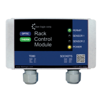
TD80™ Level Gauging and Overfill Prevention System Product Manual
Page 46 TD80 Installation/ Rev. 2, August 4, 2015
2. Horn or light to Finch FILL-NO and Electrical Ground
3. Finch Jumpers, see Figure 2-37
a. J1 to “B” position
b. J9 removed for Fill alarm, installed for Fall alarm
High-High (HH) Alarm Installation
1. Finch HH-COM to 8-28VDC POWER
2. Horn or light to Finch HH-NO and Electrical Ground
Spill/Fail Alarm Installation
1. Finch FAIL-COM to 8-28VDC POWER
2. Horn or light to Finch FAIL-NC and Electrical Ground
3. Finch Jumper J10 to “A” position, see Figure 2-37
NOTE: Once the Basic Alarm Installation Wiring is complete, refer back to section 2.1.2,
TD80 Installation Steps Overview, for clarification on the next installation step.

 Loading...