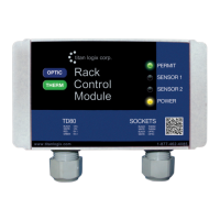
TD80™ Level Gauging and Overfill Prevention System Product Manual
Page 158 TD80 Programming/ Rev. 2, August 4, 2015
1. Measure or determine the height of the compartment. This is the total height inside,
from the bottom of the tank to the highest point where the TD80 probe is mounted.
2. Select the Probe Type of the TD80 installed
3. Select Depth and Volume units of Inches
4. Fill the Chart with the information below. This creates a linear strapping table.
a. Start value=0
b. Increment=1
c. End Value= height of compartment
5. Manually enter any remaining fractional part of the height at the end of the chart.
6. A linear depth chart is now built to act as a dipstick calibrated in inches with a
resolution of 1/16”.
7. Select the smallest spill level for the transmitter being programmed
a. 7.5” for dual rod
b. 2.5” for coaxial
8. Select a HH level 0.5” below Spill
9. Select 2 digits for Display Precision
10. Sump and Riser at 0”
11. Program the TD80
12. The TD80 is now a dipstick with measurement of inches and a resolution of 0.0625”
(1/16”).
Construct the Depth Chart
1. Set the Finch display Fill alarm to the highest level. This is the HH alarm setting.
2. Begin with an empty compartment, Finch displays 2 LO.
3. Slowly begin filling the compartment and monitor the flow meter.
4. Finch begins to display level at 5.56”, record the volume from the flow meter.
5. Continue recording volume at whole inch values 6, 7, 8, … until the HH alarm.
6. Acknowledge the HH alarm and continue recording level and volume until the Spill
alarm activates or the maximum safe volume of the compartment is reached.
7. Stop loading
8. Manually fill in the volume values between 0” and 5.56” (where 2 LO ended) with
small increments of volume. Begin with 0” and 0 volume and blend the values to the
volume at 5.56”.
9. Manually fill in the volume values from where loading stopped to the top of the
compartment with small increments of volume. Begin with the volume at 2.5” from the
top for the coaxial, 7.5” for the dual rod probe or where the loading stopped and
blend the volume up to the maximum depth and volume of the compartment.
Programming the TD80
1. Build a new strapping table in Birdfeeder using the newly created depth chart.
a. Replace the original linear strapping table inch values in the volume column
with the recorded volume at each inch.
b. Set the Spill alarm level and reset option according to customer requirements
c. Set the HH alarm level according to customer requirements
d. Riser and sump values are 0”
e. Set the 4-20mA adjustments according to customer requirements, if installed.
2. Save the strapping table
3. Program the TD80
4. Ensure that the Fill alarm is set to customer requirements while testing the
programming results.

 Loading...