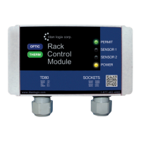
TD80™ Level Gauging and Overfill Prevention System Product Manual
Rev. 2, August 4, 2015/ TD80 Installation Page 51
iii. J10= “B” position
iv. Decimal point jumper for required Display
10. Optional Gauge Enable toggle switch red wire to GAUGE ENABLE (PTO) and black
wire to GROUND
11. Finch FAIL-COM to Relay Module FAIL-COM (6)
12. Finch HH-NO to Relay Module HH-NC (5)
13. Finch FILL-NC to Relay Module FILL-NC (4)
14. Optional Green Light to Relay Module HH-NC (5) and POWER (15), refer to Figure
2-23 & Figure 2-24
15. Optional Red Light to Relay Module HORN/RED L (8) and POWER (15), refer to
Figure 2-23 & Figure 2-24
16. Optional Horn (-) to Relay Module HORN/RED L (8), Horn (+) to Relay Module
POWER (15), refer to Figure 2-23 & Figure 2-24
17. Solenoid to Relay Module SOLENOID (7) and Electrical Ground
NOTE: Once the Overfill Prevention Installation Wiring is complete, refer back to section
2.1.2, TD80 Installation Steps Overview, for clarification on the next installation step.

 Loading...