Page 4-4 Document Ref 909342-001 Rev 11
Packaging & Handling Quantium 410 Installation Manual
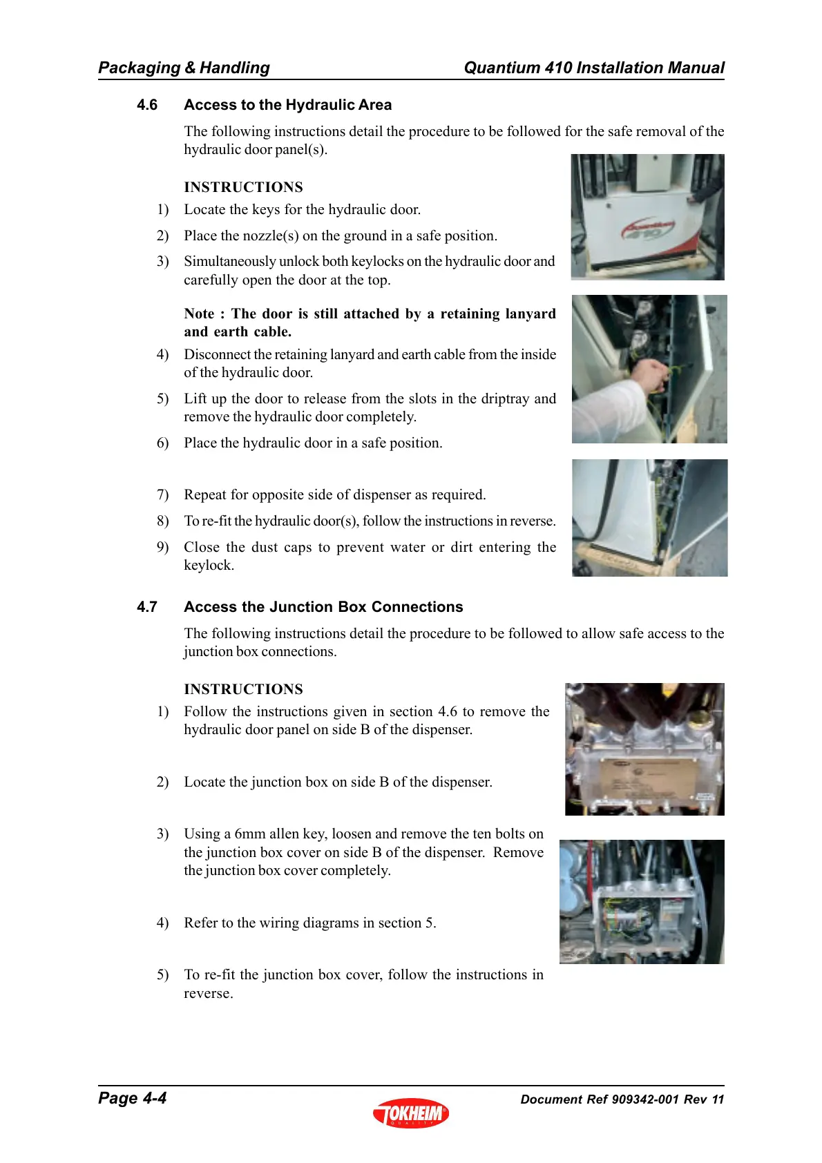
4.6 Access to the Hydraulic Area
The following instructions detail the procedure to be followed for the safe removal of the
hydraulic door panel(s).
INSTRUCTIONS
1) Locate the keys for the hydraulic door.
2) Place the nozzle(s) on the ground in a safe position.
3) Simultaneously unlock both keylocks on the hydraulic door and
carefully open the door at the top.
Note : The door is still attached by a retaining lanyard
and earth cable.
4) Disconnect the retaining lanyard and earth cable from the inside
of the hydraulic door.
5) Lift up the door to release from the slots in the driptray and
remove the hydraulic door completely.
6) Place the hydraulic door in a safe position.
7) Repeat for opposite side of dispenser as required.
8) To re-fit the hydraulic door(s), follow the instructions in reverse.
9) Close the dust caps to prevent water or dirt entering the
keylock.
4.7 Access the Junction Box Connections
The following instructions detail the procedure to be followed to allow safe access to the
junction box connections.
INSTRUCTIONS
1) Follow the instructions given in section 4.6 to remove the
hydraulic door panel on side B of the dispenser.
2) Locate the junction box on side B of the dispenser.
3) Using a 6mm allen key, loosen and remove the ten bolts on
the junction box cover on side B of the dispenser. Remove
the junction box cover completely.
4) Refer to the wiring diagrams in section 5.
5) To re-fit the junction box cover, follow the instructions in
reverse.