Document Ref 909342-001 Rev 11 Page 5-3
Quantium 410 Installation Manual Installation
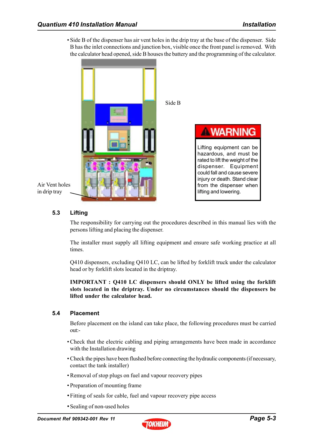
Side B
5.3 Lifting
The responsibility for carrying out the procedures described in this manual lies with the
persons lifting and placing the dispenser.
The installer must supply all lifting equipment and ensure safe working practice at all
times.
Q410 dispensers, excluding Q410 LC, can be lifted by forklift truck under the calculator
head or by forklift slots located in the driptray.
IMPORTANT : Q410 LC dispensers should ONLY be lifted using the forklift
slots located in the driptray. Under no circumstances should the dispensers be
lifted under the calculator head.
5.4 Placement
Before placement on the island can take place, the following procedures must be carried
out:-
• Check that the electric cabling and piping arrangements have been made in accordance
with the Installation drawing
• Check the pipes have been flushed before connecting the hydraulic components (if necessary,
contact the tank installer)
• Removal of stop plugs on fuel and vapour recovery pipes
• Preparation of mounting frame
• Fitting of seals for cable, fuel and vapour recovery pipe access
• Sealing of non-used holes
Lifting equipment can be
hazardous, and must be
rated to lift the weight of the
dispenser. Equipment
could fall and cause severe
injury or death. Stand clear
from the dispenser when
lifting and lowering.
• Side B of the dispenser has air vent holes in the drip tray at the base of the dispenser. Side
B has the inlet connections and junction box, visible once the front panel is removed. With
the calculator head opened, side B houses the battery and the programming of the calculator.
Air Vent holes
in drip tray