Page 5-10 Document Ref 909342-001 Rev 11
Installation Quantium 410 Installation Manual
5.5 Hydraulic Connections
Connect all hydraulic and electric junctions according to the specifications as described in
this section and indicated on the drawings in Section 3.
Flow rates achieved are dependent upon the type of submerged pumping system used and
other site-specific conditions.
Connections to the fuel supply pipes and the vapour return lines
are accessible from side B of the dispenser (see section 5.2 for
identification of sides).
The dispenser is positioned with the filter box positioned above
the relevant fuel supply risers. If required, adapters should be
fitted to the supply pipes.
Note : The maximum pressure must not exceed 3.5 bar.
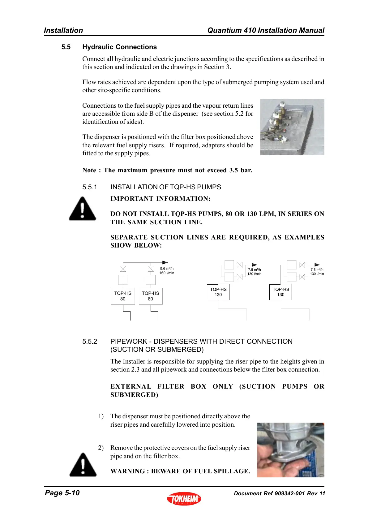
5.5.1 INSTALLATION OF TQP-HS PUMPS
IMPORTANT INFORMATION:
DO NOT INSTALL TQP-HS PUMPS, 80 OR 130 LPM, IN SERIES ON
THE SAME SUCTION LINE.
SEPARATE SUCTION LINES ARE REQUIRED, AS EXAMPLES
SHOW BELOW:
5.5.2 PIPEWORK - DISPENSERS WITH DIRECT CONNECTION
(SUCTION OR SUBMERGED)
The Installer is responsible for supplying the riser pipe to the heights given in
section 2.3 and all pipework and connections below the filter box connection.
EXTERNAL FILTER BOX ONLY (SUCTION PUMPS OR
SUBMERGED)
1) The dispenser must be positioned directly above the
riser pipes and carefully lowered into position.
2) Remove the protective covers on the fuel supply riser
pipe and on the filter box.
WARNING : BEWARE OF FUEL SPILLAGE.
TQP-HS
80
TQP-HS
80
9.6 m³/h
160 l/min