Document Ref 909342-001 Rev 11 Page 2-5
Quantium 410 Installation Manual Site Preparation
Note : The following schematics are for information purposes only and do not
represent the actual positions of the components.
Note : The Schematics show configurations where pumping units are fitted.
For submerged configurations there would be no pumping units.
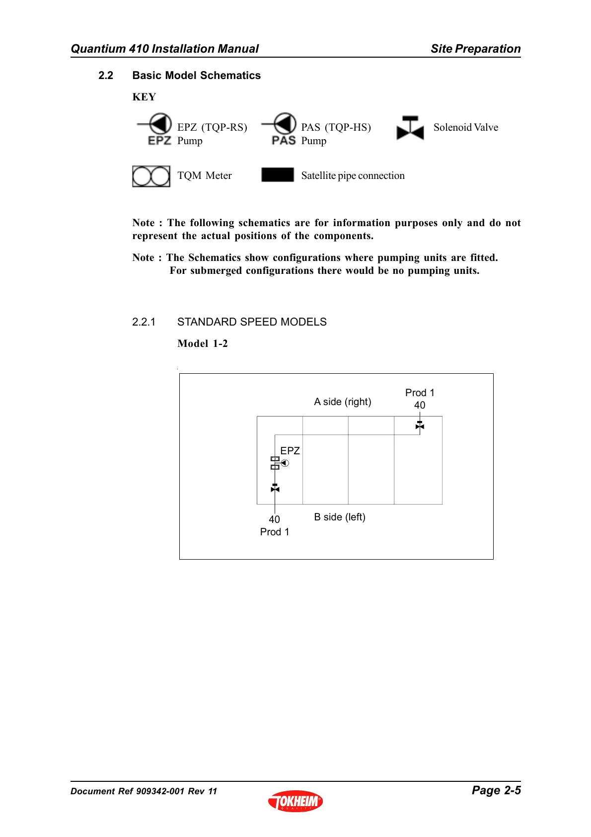
2.2.1 STANDARD SPEED MODELS
Model 1-2
2.2 Basic Model Schematics
KEY
EPZ (TQP-RS)
Pump
PAS (TQP-HS)
Pump
TQM Meter
Solenoid Valve
Satellite pipe connection
A side (right)
EPZ
B side (left)
40
Prod 1
Prod 1
40