4. Communication With a PC
71
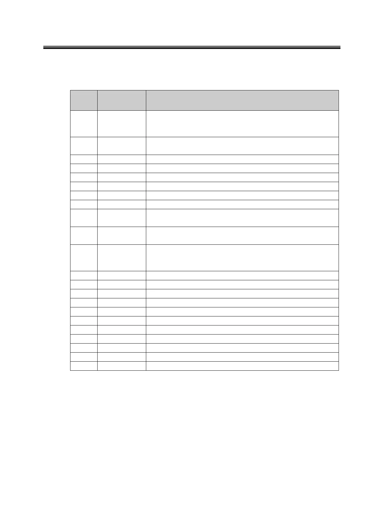
4.3 Remote Measurement Output Format
During remote measurement (ST command), the output format of data from the instrument is as
shown below.
■BM-7A Mode
Row
number
Output data
example
Data Contents
1 D1 Level of luminance of the measured object with respect to the
measurement range of the instrument
0: Normal 1: Under 2: Over
2 TS Response speed of the photo-receiver circuit
TF: FAST TS: SLOW
3 MA Measurement range MA: AUTO MM: MANUAL
4 X1 X Range (X1 to X5)
5 Y1 Y Range (Y1 to Y5)
6 Z1 Z Range (Z1 to Z5)
7 UC Unit UC: cd/㎡
8 F2 Measurement angle F1: 0.1° F2: 0.2° F3: 1.0° F4: 2.0°
9 K2 Correction factor
K0: No correction K1 to K9: Correction factor number
10 FG1 Area correction group number in area correction function
FG0: No correction FG1 to FG10: Area correction group number
11 GK0 Applicable chromaticity area in the area correction function
GK0: No applicable area
GK1 to GK5: Color data corresponding to the area
12 1.234E+56 Luminance
13 1.234E+56 Tristimulus value X
14 1.234E+56 Tristimulus value Y
15 1.234E+56 Tristimulus value Z
16 1.234 Chromaticity x
17 1.234 Chromaticity y
18 1.234 Chromaticity u’
19 1.234 Chromaticity v’
20 12345 Color temperature
21 123456 Deviation
22 END Data end command