Specifications
GR-3 Operator’s Manual
A-12
Radio (Modem) RF Connector
The modem connector (Table A-8) is a BNC RF connector for UHF
or a reverse polarity TNC connector for spread spectrum.
Power Connector
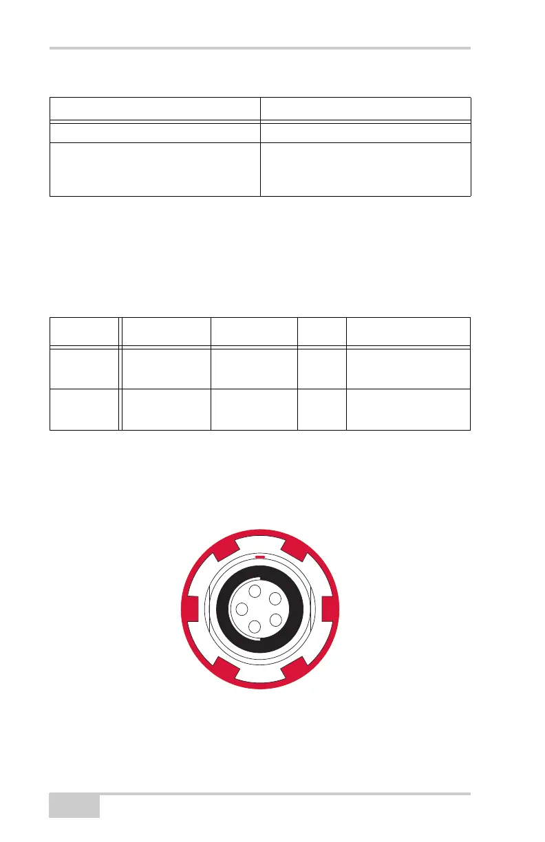
Rimmed in red, the power connector (Figure A-1) is a sealed
receptacle, 5 pin, ODU part number G80F1C-T05QF00-0000.
Figure A-1. Power Connector
Nominal output impedance 50 Ohms 2.0:1 VSWR
Output power control accuracy + 1dB (at normal test condition)
+2.0 dB and -3.0 dB (under extreme test
condition)
Table A-8. Modem Connector Specifications
Modem Type Signal Type Dir Details
UHF BNC Modem I/O I/O RF/GSM output from
modem antenna
Spread
Spectrum
Reverse
polarity TNC
Modem I/O I/O RF/GSM output from
modem antenna
Table A-7. Digital UHF Receiver Specifications
Parameter Specification