Specifications
GR-3 Operator’s Manual
A-14
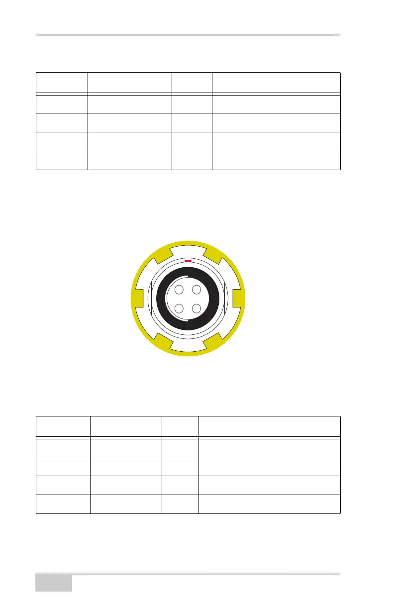
USB Connector
Rimmed in yellow, the USB connector is a sealed receptacle, 4 pin
TPS cable connector (Figure A-3).
Figure A-3. USB Connector for GGD Options
Table A-11 gives the USB connector specifications.
4 RTS O Request to send
5 RXD I Receive data
6 TXD O Transmit data
7 Not used
Table A-11. USB Specifications
Number Signal Name Dir Details
1 USB_PWR P Bus power input
2 USB D- I/O Data minus
3 USB D+ I/O Data plus
4 GND - Ground
Table A-10. RS232 Connector Specifications (Continued)
Number Signal Name Dir Details