MINTER Configuration
P/N 7010-0736
3-35
Once the receiver is configured, the configuration remains until
you change it using PC-CDU/TopSURV/Pocket-3D or clearing
the NVRAM.
For more details on the settings available for configuring the Base
and Rover receivers, refer to the PC-CDU Reference Manual.
14. Continue with other configuration activities or click File
Disconnect, then FileExit to quit PC-CDU. Disconnecting
before exiting ensures proper port management.
MINTER Configuration
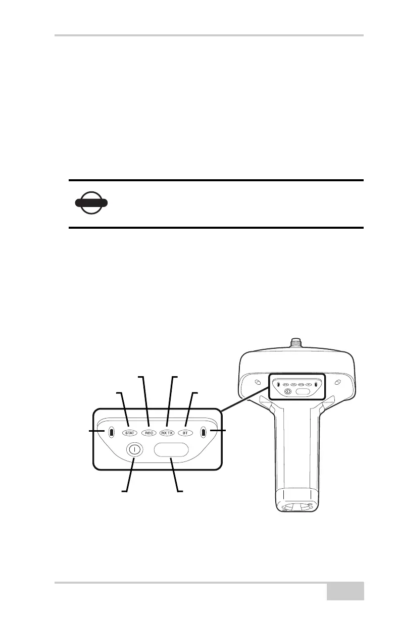
The Minimum INTERface (MINTER) consists of two keys (power
and FUNCTION) that control the receiver’s operation, four LEDs
(STAT, REC, RX/TX, and BT) that display the receiver’s operational
status, and two LEDs that display the battery status (Figure 3-29).
Figure 3-29. MINTER
Disconnect the receiver from PC-CDU before
exiting to eliminate possible conflicts with the
management of the computer’s serial ports.
FUNCTION
FUNCTION
Battery
STAT
REC RX TX
BT
Power
Button
FUNCTION
Button
Battery