Introduction
GR-3 Operator’s Manual
1-16
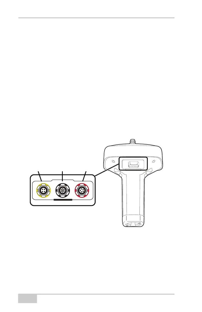
Data and Power Ports
The GR-3 has the following three ports (Figure 1-6):
• USB – rimmed in yellow; used for high-speed data transfer and
communication between the receiver and an external device.
The body of the connector on the corresponding cable is yellow.
• Serial – rimmed in black; used for communication between the
receiver and an external device.
The body of the connector on the corresponding cable is black.
• Power – rimmed in red; used to connect the receiver to an
external power source. This port can also be used to charge the
batteries.
The body of the connector on the corresponding cable is red.
Figure 1-6. GR-3 Ports
External Radio Antenna Connector
The UHF and SS antennas connect to the external antenna connector
on the GR-3 radome (Figure 1-7). Both modem antenna types include
support for a GSM modem.
U
S
B
S
E
R
I
A
L
P
O
W
E
R
USB
(yellow)
Power
(red)
Serial
(black)