Setup Verification
Troubleshooting
44
X-52/X-72 2D Excavator Installation and Calibration Manual P/N: 1022461-01
5. If the measurements compared against 3D-MC match, there could be an issue with one of the
other sensors; repeat steps 1-4 and reverify.
6. If the measurements compared against 3D-MC still match, check the tilt bucket sensor (if used),
and then follow the steps in
“Stick Sensor” below.
7. If the measurements compared against 3D-MC do not match, each sensor must be evaluated for
machine measurement or calibration errors.
Stick Sensor
1. Position the bucket above the string line so that the bucket teeth or edge are at their closest
point to the string.
2. Place the bucket teeth or edge on the string, and zero the bucket in 3D-MC.
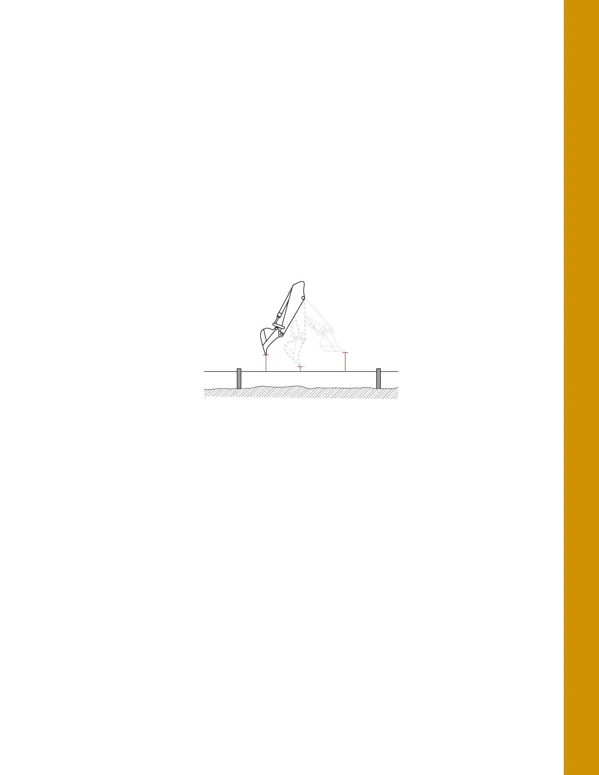
3. Curl only the stick in and out at various positions, and measure the distance from the string line
to the bucket teeth with a measuring tape (
Figure 53).
Figure 53: String Line Verification - Stick
4. Compare the measuring tape values with those shown in 3D-MC.
5. If the measurements compared against 3D-MC match, there could be an issue with one of the
other sensors; repeat steps 1-4 and reverify.
6. If the measurements compared against 3D-MC still match, follow the steps in “Boom Sensor”
below.
7. If the measurements compared against 3D-MC do not match, each sensor must be evaluated for
machine measurement or calibration errors.
Boom Sensor
1. Position the bucket above the string line so that the bucket teeth or edge are at their closest
point to the string.
2. Place the bucket teeth or edge on the string, and zero the bucket in 3D-MC.