Calibration
25
X-52/X-72 2D Excavator Installation and Calibration Manual P/N: 1022461-01
Calibration
Before calibrating the sensors, note the following:
Body Sensor
Once the sensors are named, assigned to a machine element, and the orientation is selected, calibrate
each sensor using 3D-MC. A sensor calibration can be performed at any time.
1. In 3D-MC, tap Topcon Menu Button Control Machine setup.
2. Select the appropriate machine file, and tap Edit.
3. Continue to press Next to access the Excavator Frame/Sensors screen.
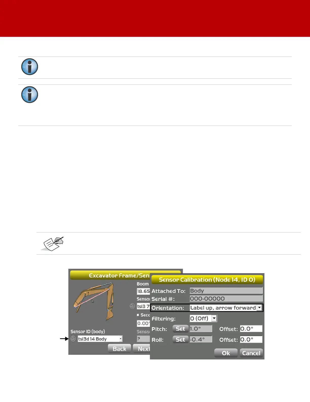
4. Tap the Wrench icon for the body sensor.
5. Tap the Orientation box, and select the physical orientation of the mounted sensor; tap OK.
Figure 28: Select Sensor Orientation
If using the DogBone mounting option, worn joints in the DogBone linkage will cause decreased
accuracy.
The best practice is to perform the machine calibrations as ordered in this manual. Performing
the calibrations out of order will not affect system performance.
There are two exceptions to this rule when using a DogBone sensor:
a. You must calibrate the stick sensor before calibrating the DogBone sensor.
b. When using a tilt bucket sensor you must calibrate the attachment/doggone sensor before
calibrating the tilt bucket sensor.
Orientation is Label up with the arrow pointing one of the four directions.