Calibration
Calibrating the LS-B10W
40
X-52/X-72 2D Excavator Installation and Calibration Manual P/N: 1022461-01
4. Navigate through the remaining steps of Machine Setup, then save the file and exit 3D-MC.
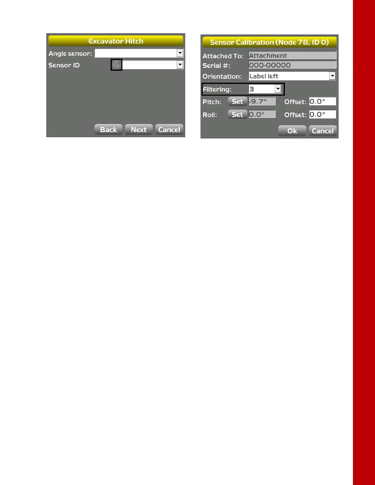
Figure 49: Set Filtering Level
Calibrating the LS-B10W
To calibrate the LS-B10W Laser Receiver, determine the position of the receiver on the stick. After
calibrating the sensor, 3D-MC will determine the angle of the LS-B10W to the stick center line.
1. Position the machine on a stable surface free of obstructions, and rotate the body to 0.0° roll.
2. Orient the stick so that the LS-B10W is positioned vertically.
3. In 3D-MC, tap Topcon Menu ButtonControlMachine setup. Select the applicable
machine file for the job, and tap Edit.
4. Tap Next to navigate to the Laser Receiver (LSB10W) screen.
5. Enter the following measurements for the LS-B10W (Figure 50).
• Depth to center of stick – enter the measurement for the distance between the middle of
the stick to the light cells on the LS-B10W.
• From bucket pivot – enter the measurement for the distance from the along the projected
line between the bucket pivot and stick pivot at the point where the LS-B10W is perpendicular
to the projected line (Figure 50).
• Left of pivot line – enter the measurement for the distance between the mark on the LS-
B10W and the pivot line. If right of pivot line, use a negative value.
6. Make sure the LS-B10W Laser Receiver is vertical, and then tap Calibrate to determine the
angle between the stick and the LS-B10W (
Figure 50).