Do you have a question about the Topcon X-52 and is the answer not in the manual?
Outlines the usage rights, copyright, and intellectual property of the manual content.
Lists registered and unregistered trademarks of Topcon and other companies mentioned.
States the product is provided "as-is" and disclaims implied warranties like merchantability or fitness.
Details the terms for using the software supplied with the product.
Defines the confidential nature of the manual and software information provided by TPS.
Highlights potential risks of improper product use and the need for authorized repairs.
Explains the typographical conventions and icons used throughout the manual for clarity.
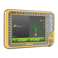
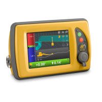
Lists and illustrates the hardware and software components of the 2D indicate systems.
Guides users on accessing the MC-X1 web interface via a computer's IP address.
Alternative method to connect to the MC-X web interface using MCXCONFIG software.
Step-by-step instructions for updating the firmware of the MC-X1 controller.
Procedures for resetting the MC-X1 controller to its default settings.
Details the installation and mounting of TS-i3 tilt sensors on various excavator parts.
Specific mounting instructions and considerations for the hitch sensor.
Describes an alternative mounting location for the hitch sensor on the DogBone.
Instructions for mounting an additional sensor on the bucket for tilt functionality.
Guidelines for installing the TS-i3 sensor on the excavator's stick.
Procedures for mounting the TS-i3 sensor parallel to the boom center.
Information on mounting a sensor for a secondary boom configuration.
Instructions for mounting the dual-axis TS-i3 body sensor on the excavator's body.
Information on mounting the LS-B10W Laser Receiver and its bracket on the stick.
Guidance on installing the MC-X1 Controller onto the machine's body.
Important notes and considerations before measuring and configuring machine dimensions.
Configuration steps specific to the GR-i3 component, including IMU mounting.
Details on measuring and configuring the body and boom sensor IDs and lengths.
Configuration for the stick sensor ID and stick length.
Configuration steps for the hitch sensor, including mounting location selection.
Measurements and configuration for the DogBone sensor.
Procedures for setting up various excavator attachments, including width and length.
Entering measurements for the LS-B10W laser receiver.
Process for inputting sensor serial numbers and orientation into the system.
Guides on setting up display indicators for machine status and guidance.
Final step to save the machine configuration settings.
Detailed steps for calibrating the body sensor, including pitch and roll adjustments.
Instructions for calibrating the boom sensor, often using a laser for zero degrees.
Method for calibrating the secondary boom sensor, similar to the primary boom sensor.
Steps for calibrating the stick sensor, typically positioning the stick at -90 degrees.
Calibration procedure for the hitch sensor, with options for DogBone or quick-release.
Specific calibration steps for the DogBone sensor, involving stick sensor comparison.
Calibration procedure for the hitch sensor when mounted on the hitch or quick-coupling.
Calibrating the edge of the attachment for accurate measurements.
Guidelines for performing calibrations when using multiple attachments.
Calibration process for a tilt bucket attachment, involving pitch and roll adjustments.
Explains the need for a hard terminator for the last sensor in the CAN communication chain.
How to adjust sensor filtering levels to manage reaction speed and damping.
Instructions for taking specific measurements for the LS-B10W receiver's position on the stick.
A test procedure using a string line to verify the accuracy of the excavator system.
Verifies the functionality and accuracy of the LS-B10W laser receiver.
Troubleshooting steps specifically for issues related to the hitch sensor.
Troubleshooting steps for problems encountered with the stick sensor.
Troubleshooting steps for issues identified with the boom sensor.
Provides essential safety precautions for installing and using Topcon components on excavators.
Safety advisory regarding RF exposure and minimum installation distances for antennas.
Details compliance with Canadian regulations, including IC Statements.
Specifies the input voltage requirements and functional range for the system.
Information on accessing licenses and source code for open-source software used in the product.
| Brand | Topcon |
|---|---|
| Model | X-52 |
| Category | Excavators |
| Language | English |