Introduction
1
X-52/X-72 2D Excavator Installation and Calibration Manual P/N: 1022461-01
Introduction
This manual discusses how to install and calibrate Topcon’s X-52 and X-72 2D Excavator Systems utilizing
the MC-X1 Controller.
The TS-i3 sensors used in the Topcon excavator systems measure the pitch and roll angle of various
machine elements. Each sensor accurately measures a gravity-referenced angle of the body, boom, stick,
and attachment, sending this angle data to a GX-55/GX-75 display to provide precise grade. Each sensor
is configured and calibrated for its specific location on the excavator.
The body sensor functionality is unique as it measures both pitch and roll (cross slope) of the machine.
X-52 and X-72 System Components
Tabl e 1 lists the hardware and software components of the 2D indicate systems.
The TS-i3 Tilt Sensors, the MC-X1 Controller, the GX-55/GX-75 display, and the LS-B10W Laser Receiver
make up the 2D indicate system. The LS-B10W adds a laser height reference, and is calibrated for its
location on the stick of the excavator.
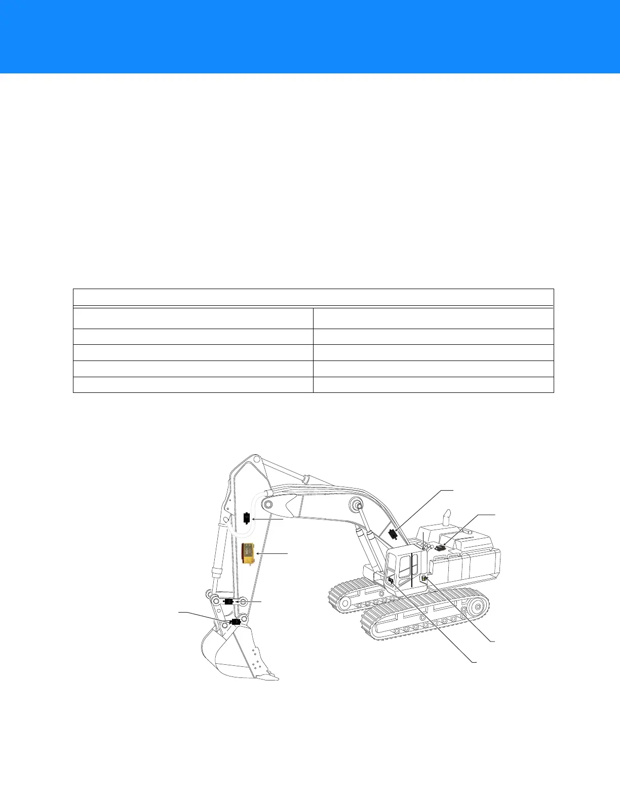
Figure 1: Machine Components of the X-52 and X-72 System
Table 1. 2D Indicate System Components
X-52 /X-72
Hardware Software
TS-i3 Tilt Sensors 3D-MC V12.2.4 or later
GX-55/GX-75 Display MCXCONFIG
MC-X1 Controller
LS-B110W Laser Receiver
Optional
Hitch Sensor
Mounting Location:
DogBone
Optional
Hitch Sensor
Mounting Location:
Hitch/Coupling
LS-B10WLS-B10W
Laser ReceiverLaser Receiver
LS-B10W
Laser Receiver
Body Sensor
Boom
Boom
SensorSensor
Boom Sensor
StickStick
SensorSensor
Stick
Sensor
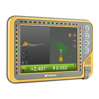
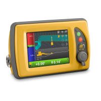
GX-55/GX-75
Display
MC-X1 Controller
7400 National DriveLivermore, CA 94551
P/N: 1015925-01
S/N: 1420-XXXXX
Contains FCC ID:
Z64-WL18DBMOD
Contains: IC: