Introduction
X-52 and X-72 System Components
2
X-52/X-72 2D Excavator Installation and Calibration Manual P/N: 1022461-01
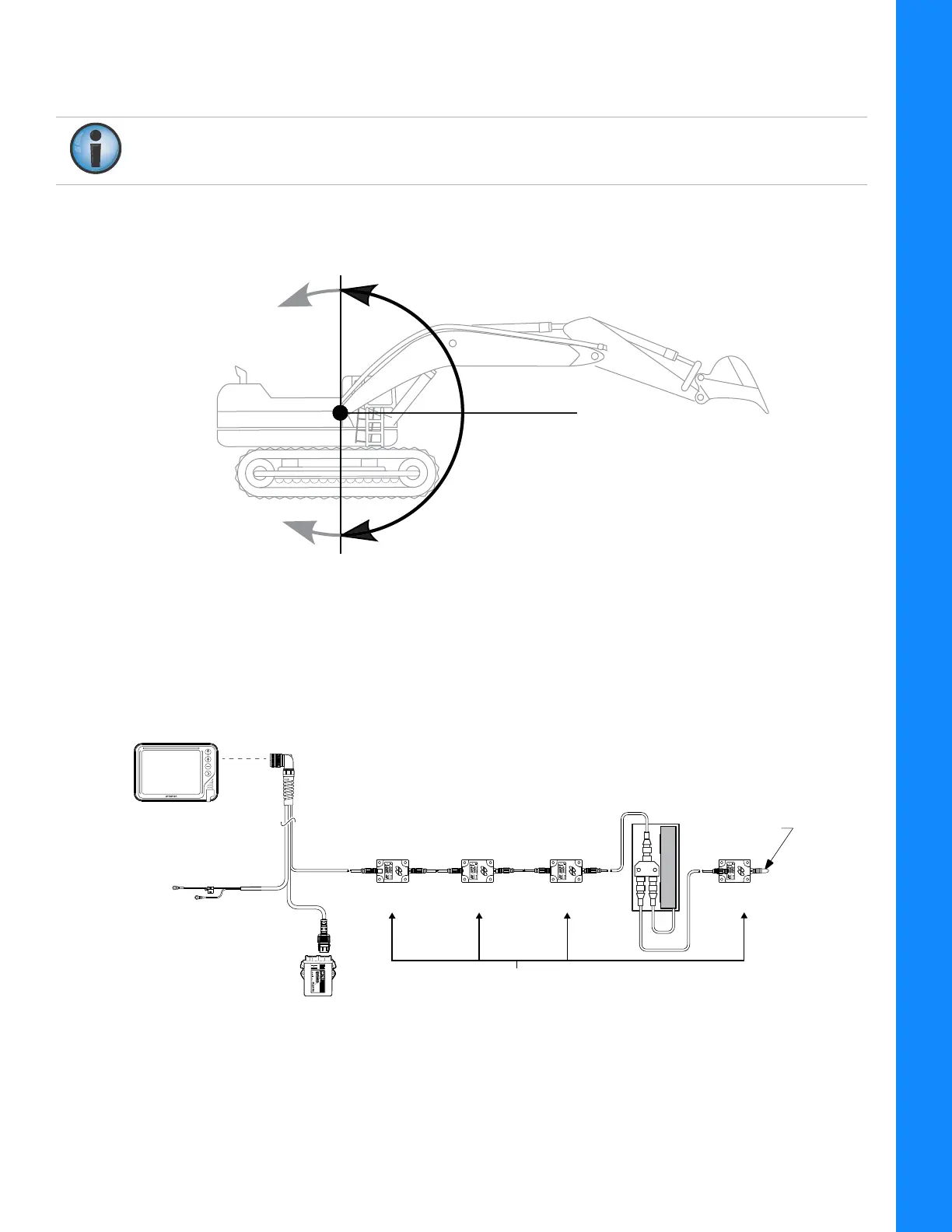
Figure 3 shows the basic cabling connections for the 2D excavator system. When installing
components, use the Topcon supplied fuse or f
used power from the machine of the same rating.
Sitting in the cab facing forward, the sensor angles are 0° straight ahead
(horizontal), +90° straight
up, and -90° directly down (Figure 2).
Figure 2: Angle Convention Used For Tilt Sensors
Figure 3: Basic Cable Connections
f
or the GX Series System
System ground must be connected to the frame side of the ground disconnect switch, not
directly to the negative battery terminal.
TS-
i3 Tilt Sensors
Body Boom
Stick
Bucket
LS-B10W
Laser Receiver
And Bracket
Ground To Chassis
7.5 Amp In-line Fuse Required
Voltage Supply
(Switched or Unswitched)
-
+
Sensor
Terminator
GX Series Display
MC-X1
Controller
7400 National Drive
Livermore, CA 94551
P/N: 1015925-01
S/N: 1420-XXXXX
Contains FCC ID: Z64-WL18DBMOD
Contains: IC: 451I-WL18DBMOD
FCC ID: WR4-15925 IC: 6050B-15925