2.3.1.2 Media Dependent Ethernet Reference Schematics
Ethernet connectors with integrated magnetics are preferable. If a design with external magnetics
is chosen, additional care must be taken to route the signals between the magnetics and Ethernet
connector. If only a fast Ethernet (100Mbit/s) is required, some design costs may be saved by using
only 10/100Base-TX magnetics.
The magnetics provide a certain ESD protection which is enough for many designs. However,
especially in Power over Ethernet (PoE) systems, additional transient voltage suppressor diodes
(TVS) are highly recommended to be placed between the module and the magnetics. More
information can be found in the following application note from Microchip:
http://ww1.microchip.com/downloads/en/AppNotes/00002157B.pdf
The LED output signals ETH_1_ACT and ETH_1_LINK are 3.3V tolerant open drain signals with no
pull-up resistor on the module. The pins can be connected directly to the LED of the Ethernet jack
with suitable series resistors. There is no need for additional buffering if the current drawn does
not exceeds 10mA. The ETH_1_ACT signal is used as reference for the ETH_1_MDI2_P signal on
the SODIMM connector and the ETH_1_LINK is a reference for the ETH_1_MDI1_P signal.
Therefore, it is recommended to add a strapping capacitor of 1nF to GND as close as possible to
the SODIMM connector.
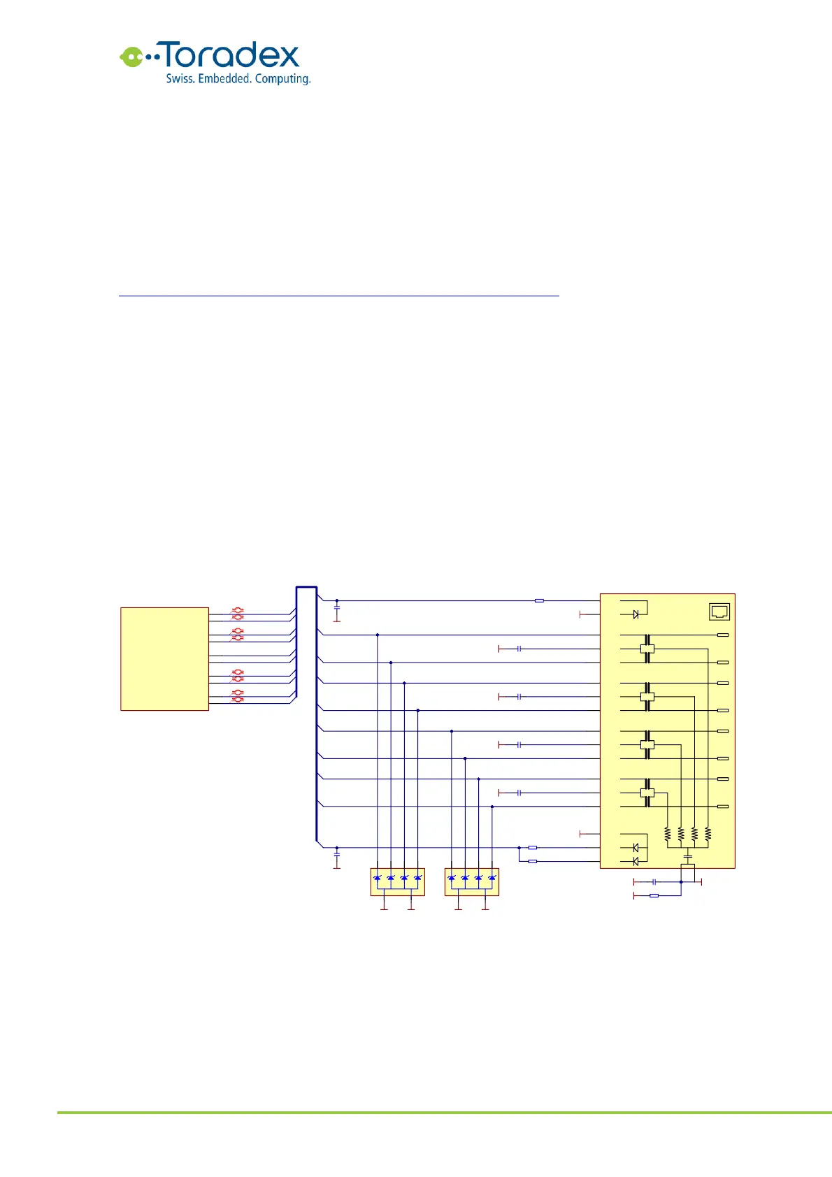
2.3.1.2.1 Gigabit Ethernet Schematic Example (Integrated Magnetics)
The Verdin module does not require a center tap voltage. Therefore, add individual 100nF
capacitors to the center taps of the magnetics. Do not connect the center taps together.
The Ethernet connector with integrated magnetics provides a certain amount of protection against
ESD. If a higher level is required, optional ESD protection diodes are recommended.
Figure 11: Gigabit Ethernet with integrated magnetics reference schematic
2.3.1.2.2 Gigabit Ethernet Schematic Example (Discrete Magnetics)
If discrete magnetics are used instead of a RJ-45 Ethernet jack with integrated magnetics, special
care must be taken to route the signals between the magnetics and the jack. These signals are
required to be high voltage isolated from the other signals. Therefore, it is necessary to place a
dedicated ground plane under these signals which has a minimum separation of 2mm from every
other signal and plane. Try to place the magnetics as close as possible to the Ethernet jack. This
reduces the length of the signal traces between the magnetics and jack.