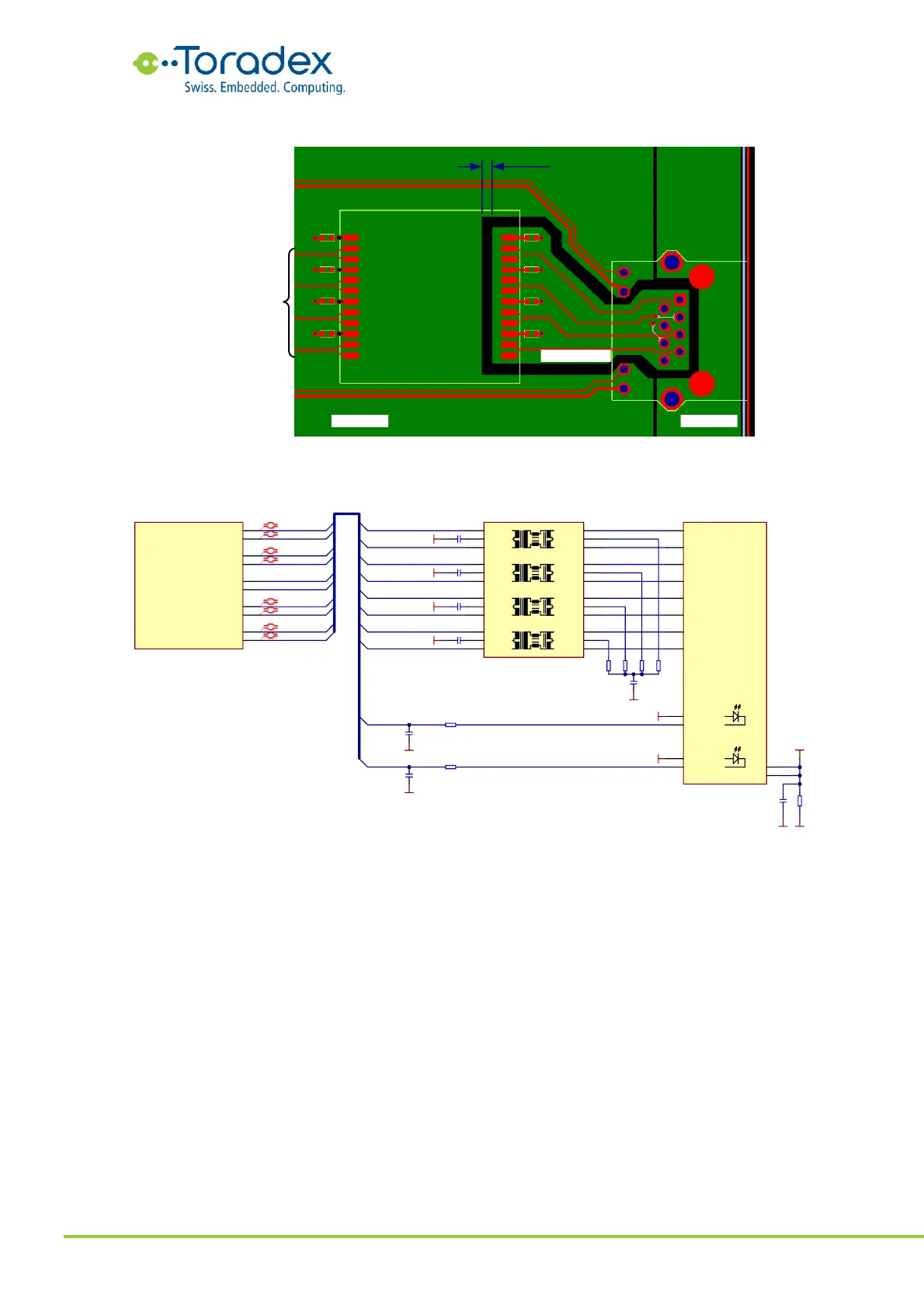
Figure 12: Separation of magnetics ground
Figure 13: Gigabit Ethernet with discrete magnetics reference schematic
2.3.1.2.3 10/100Mbit Ethernet Schematic Example (Integrated Magnetics)
The Fast Ethernet interface uses the MDI0 as transmitting lanes and the MDI1 as receiving lane. As
most Ethernet PHYs feature Auto-MDIX, the signal direction RX and TX could be swapped.
However, it is recommending not swapping the RX and TX lanes in order to ensure compatibility
between all Verdin modules.
The MDI2 and MDI3 lanes are not used for the 10/100Base-TX interface. These signals can be left
unconnected.