Verdin Carrier Board Design Guide
Preliminary – Subject to Change
Toradex AG l Ebenaustrasse 10 l 6048 Horw l Switzerland l +41 41 500 48 00 l www.toradex.com l info@toradex.com
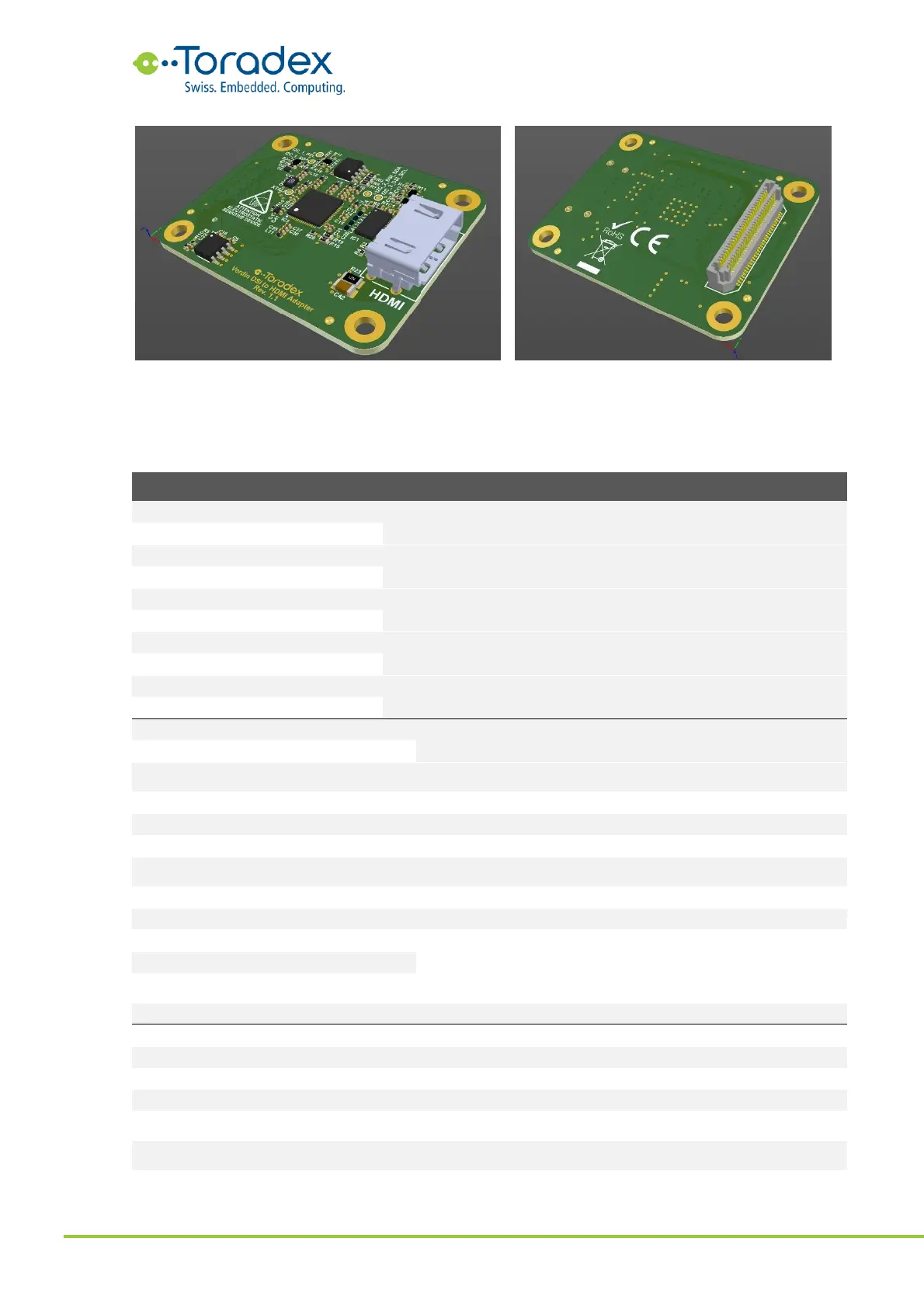
Figure 33: Front and back side of Verdin DSI to HDMI Adapter
The following table contains the pinout of the MIPI DSI display adapter connector and its
recommended connection on the carrier board. The direction is indicated from the adapter point of
view.
MIPI DSI differential clock
MIPI DSI differential data lane 0
MIPI DSI differential data lane 1
MIPI DSI differential data lane 2
MIPI DSI differential data lane 3
I
2
C interface, intended to be used as DDC
Dedicated PWM for the display backlight brightness
control, could also be used as general-purpose IO
Dedicated general-purpose IO for DSI bridges
Dedicated general-purpose IO for DSI bridges
Serial audio input data stream to the Verdin Module
Serial audio output data stream from the Verdin
Module
Synchronization/ field select/ left-right channel select
General purpose I
2
C interface, intended to be used for
controlling the bridge IC and the touch interface
Power enable signal for the bridge
3, 10, 16, 22, 28,
34, 40, 50, 55, 60
Table 16: MIP DSI display adapter